D-serie level 1 EN.pdf - 第108页
C&P6/12 Placement Heads Settings Determining the Zero Point Correction for the C&P Head Star Axis S tuden t Guide Advanced Level 1 SIPLACE D-Series C&P6/12 Placement Heads EN 05/2007 6-28 6.3.4 Determining th…
C&P6/12 Placement Heads
Overview of Settings for C&P12 Settings
Student Guide Advanced Level 1 SIPLACE D-Series
EN 05/2007 C&P6/12 Placement Heads
6-27
6.3.2 Overview of Settings for C&P12
6.3.3 Settings for C&P Head - Details
The zero point correction for the star axis is so significant that it will be described separately below.
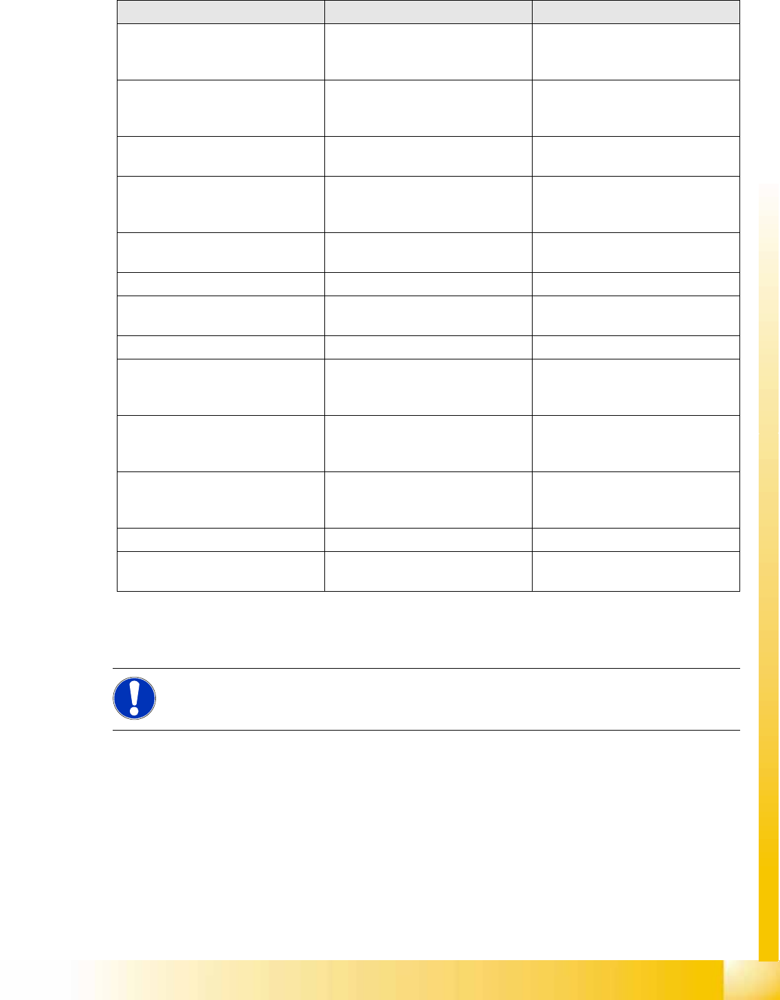
Description Tools &Equipment Adjustments
Mounting the star onto the motor
shaft of the star motor
Adjustment with the power pack and
the gauge for the star
Check the magnetic neutral position
in SITEST.
(max. deviation 95 digits)
Determine zero point correction for
the star
Gauge for zero point correction /
SITEST
Determine zero point correction
value in SITEST
--> enter positions.
Switch position on star motor
(resolution of track signals 10 - 25)
None HF/X/D machines at switch position
25
DP-axis Incremental encoder
adjustment to the glass scale
(segment)
Parallel pin 1,4 - 1,6 mm Distance 1,5 mm
Adjustment mechanical position of
valve positioning drives
Distance gauge 0.2 mm 0.2 mm distance plunger to the valve
frame
Light barrier bottom position Z-axis Parallel pin 1,0 mm Distance 1,0 mm
Clamping device on Z-belt Tension jack must lie on the belt
teeth at the top and bottom.
Belt tension of the Z-axis Belt tension device Belt tension 280 +/- 5 Hz
Setting the stop for the Z-axis Gauge for the Z end stopper
[03019865-xx]
Correct position are necessary to
determine the zero point correction
Z-axis.
Mechanical adjustments air blast
tubes on the star
Check with your eyes Check the distance between
incremental encoder DP and air blast
tubes.
Adjustments tube for air blast supply feeler gauge Air blast tubes should be approx. 0,7
mm over the frame of the circular
guide
Adjustments air pressure values Compressed air testing device 150 mbar on open 9x4 nozzle
reject circuit (not used for reject at
HF and X machine)
250 mbar (200 - 300 mbar) The reject circuit does not have a
sensor
NOTE:
For a detailed description of the C&P6/12 head settings, refer to the D-series service manuals,
in chapter
Settings --> C&P heads
.
C&P6/12 Placement Heads
Settings Determining the Zero Point Correction for the C&P Head Star Axis
Student Guide Advanced Level 1 SIPLACE D-Series
C&P6/12 Placement Heads EN 05/2007
6-28
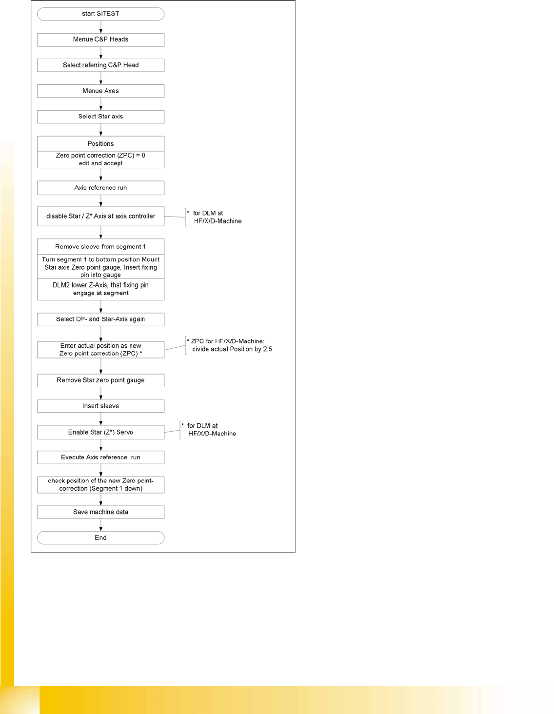
6.3.4 Determining the Zero Point Correction for the C&P Head Star Axis
6-31: Flow diagram for zero point correction
During this process, make sure you adhere to the
procedure exactly and observe the comments
about the individual steps.

C&P6/12 Placement Heads
Throughput Test for Vacuum-Holding Circuit Settings
Student Guide Advanced Level 1 SIPLACE D-Series
EN 05/2007 C&P6/12 Placement Heads
6-29
6.3.5 Throughput Test for Vacuum-Holding Circuit
Through the installation of the placement head, the silicon tube for supplying the holding circuit with
vacuum can become jammed, especially in HF/X/D3 machines.
The lower throughput reduces the holding force for the components during the placement process. This
means that components can be displaced on the nozzle, both before and after the component camera.
If this happens before the camera, the component may be moved out of the pickup tolerance. After the
camera, displacement can lead to random, uncorrectable placement offsets.
This fault can be recognized with the SITEST 'throughput test".
C&P12/6
Perform the following steps:
X Return all C&P head nozzles.
X Measure the holding circuit vacuum. Typical values are around 900 mbar (values over 900 are
shown as 900).
X Open a segment in the reject circuit and
X step the star one position.
X Measure the holding circuit vacuum. Values higher than 800 mbar are OK.
X Open another segment in the reject circuit and
X step the star one position.
X Measure the holding circuit vacuum. Values higher than 700 mbar are OK.
Values around 600 mbar are reached at around half the diameter of the silicon supply tube.
Vacuum values in the holding circuit which only reach 500 mbar are no longer sufficient to guarantee the
holding circuit function. (Values under 400 mbar are only shown as -1)