D-serie level 1 EN.pdf - 第109页
C&P6/12 Placement Heads Throughput Test for Vacuum-Holding Circuit Set tings S tude nt Guide Advanced Level 1 SIPLACE D-Series EN 05/2 007 C&P6/12 Placement Heads 6-29 6.3.5 Throughput T est for V acuum-Holding C…
C&P6/12 Placement Heads
Settings Determining the Zero Point Correction for the C&P Head Star Axis
Student Guide Advanced Level 1 SIPLACE D-Series
C&P6/12 Placement Heads EN 05/2007
6-28
6.3.4 Determining the Zero Point Correction for the C&P Head Star Axis
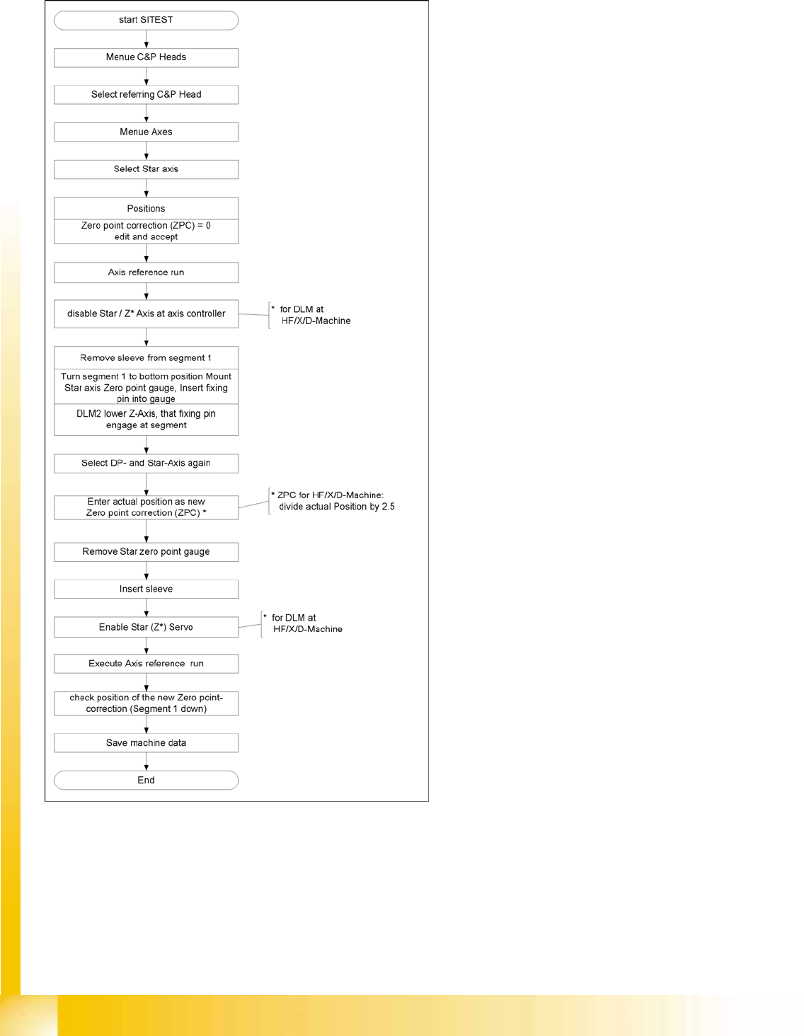
6-31: Flow diagram for zero point correction
During this process, make sure you adhere to the
procedure exactly and observe the comments
about the individual steps.

C&P6/12 Placement Heads
Throughput Test for Vacuum-Holding Circuit Settings
Student Guide Advanced Level 1 SIPLACE D-Series
EN 05/2007 C&P6/12 Placement Heads
6-29
6.3.5 Throughput Test for Vacuum-Holding Circuit
Through the installation of the placement head, the silicon tube for supplying the holding circuit with
vacuum can become jammed, especially in HF/X/D3 machines.
The lower throughput reduces the holding force for the components during the placement process. This
means that components can be displaced on the nozzle, both before and after the component camera.
If this happens before the camera, the component may be moved out of the pickup tolerance. After the
camera, displacement can lead to random, uncorrectable placement offsets.
This fault can be recognized with the SITEST 'throughput test".
C&P12/6
Perform the following steps:
X Return all C&P head nozzles.
X Measure the holding circuit vacuum. Typical values are around 900 mbar (values over 900 are
shown as 900).
X Open a segment in the reject circuit and
X step the star one position.
X Measure the holding circuit vacuum. Values higher than 800 mbar are OK.
X Open another segment in the reject circuit and
X step the star one position.
X Measure the holding circuit vacuum. Values higher than 700 mbar are OK.
Values around 600 mbar are reached at around half the diameter of the silicon supply tube.
Vacuum values in the holding circuit which only reach 500 mbar are no longer sufficient to guarantee the
holding circuit function. (Values under 400 mbar are only shown as -1)
C&P6/12 Placement Heads
Nozzle Changer Nozzle Changer for 12 Segment C&P Head
Student Guide Advanced Level 1 SIPLACE D-Series
C&P6/12 Placement Heads EN 05/2007
6-30
6.4 Nozzle Changer
The installation of a nozzle changer (NC) enables the C&P12 to be equipped quickly and automatically
with the optimum nozzle configuration, after a job changeover, and adjusted to the specific requirements
of the placement process.
6.4.1 Nozzle Changer for 12 Segment C&P Head
The nozzle changer consists of at least one and up to five magazines, each of which is equipped with
up to twelve nozzle garages. The waffle pack trays are seated on a special support and each tray is
centered using two parallel pins and is fixed in place with a spring hook.
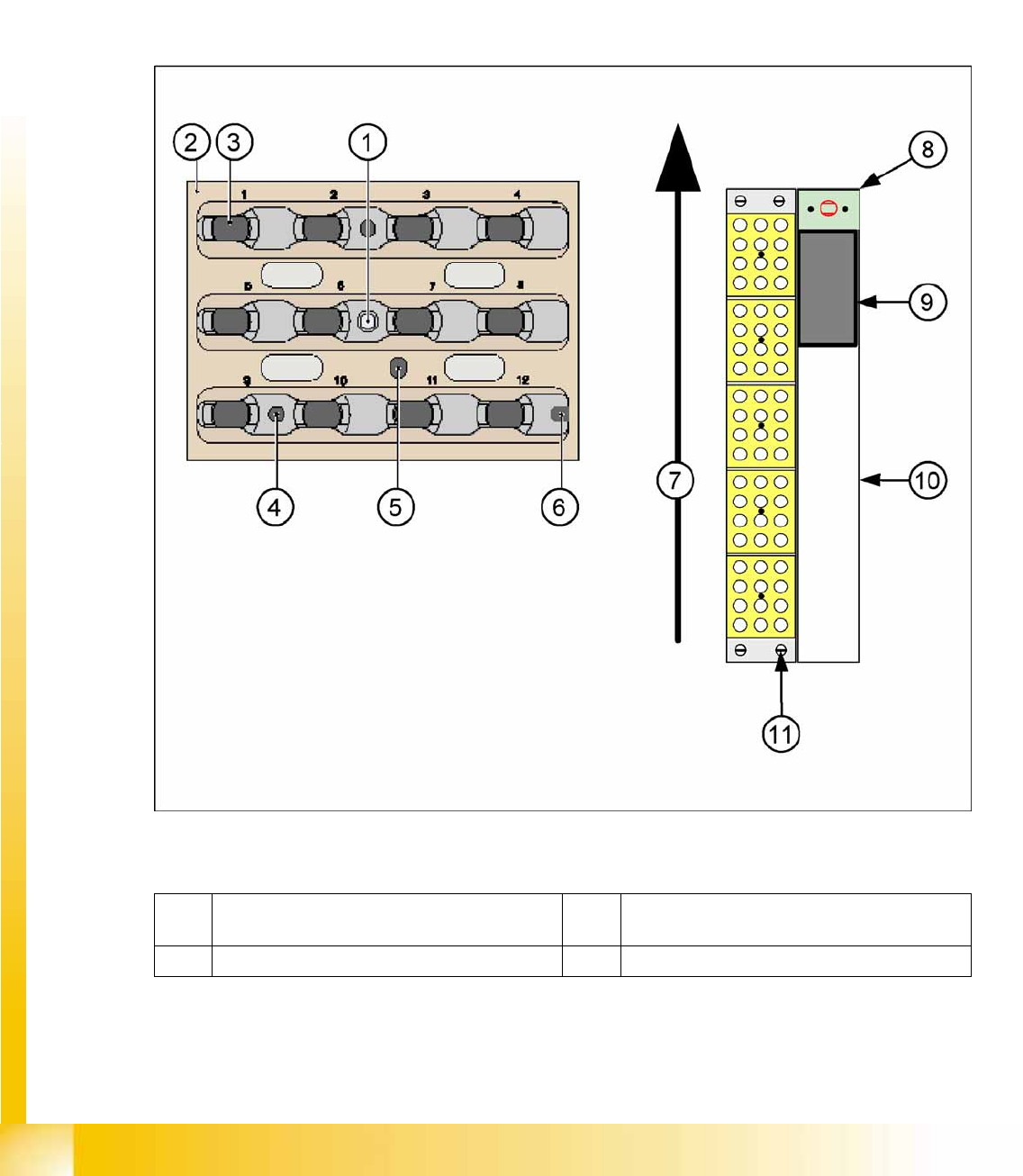
6-32: Nozzle changer and nozzle magazine for C&P12 (D4 shown as example)
Legend
1 Calibration fiducial in the waffle pack tray 6 Slit for centering pin, for exact positioning of
magazine
2 Locking plate 7 Transport direction