D-serie level 1 EN.pdf - 第119页
P&P and TWIN Heads TWIN Head Placement Principle TWIN Head Pickup and Place Cycle S tude nt Guide Advanced Level 1 SIPLACE D-Series EN 05/2007 P&P and TWIN Heads 7-5 7.2 TWIN Head Pickup and Place Cycle 7.2.1 TWI…
P&P and TWIN Heads
Overview TWIN Head Vacuum Generator
Student Guide Advanced Level 1 SIPLACE D-Series
P&P and TWIN Heads EN 05/2007
7-4
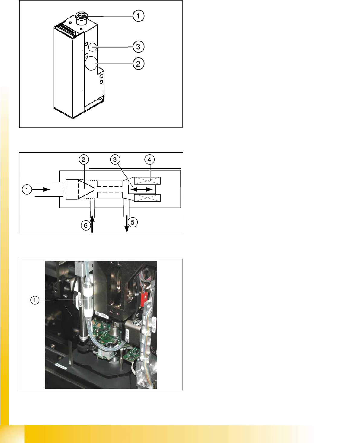
7.1.3 TWIN Head Vacuum Generator
7-1: Vacuum generator
The vacuum generator automatically controls the
vacuum, air blast and the zero balancing position
(middle position-->no vacuum and no air blast) for
the segments, with the aid of an iron core and
inductor.
Legend
1. Compressed air input
2. Exhaust to the silencer and cooling for the X-
linear motor
3. Output vacuum - vacuum is passed through
the D-axis motor shaft and then to the nozzle.
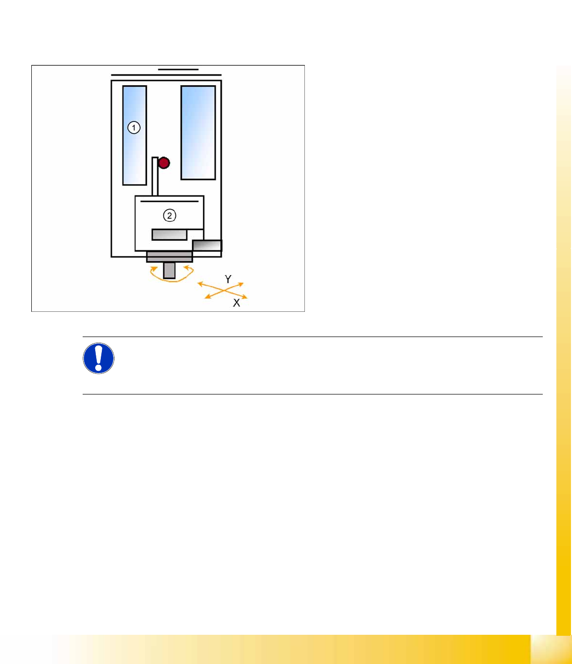
7-2: Principle of the vacuum generator
Legend
1. Compressed air input
2. Venturi nozzle
3. Plunger (iron core)
4. Plunger drive (inductor)
5. Exhaust to silencer
6. Vacuum air blast output
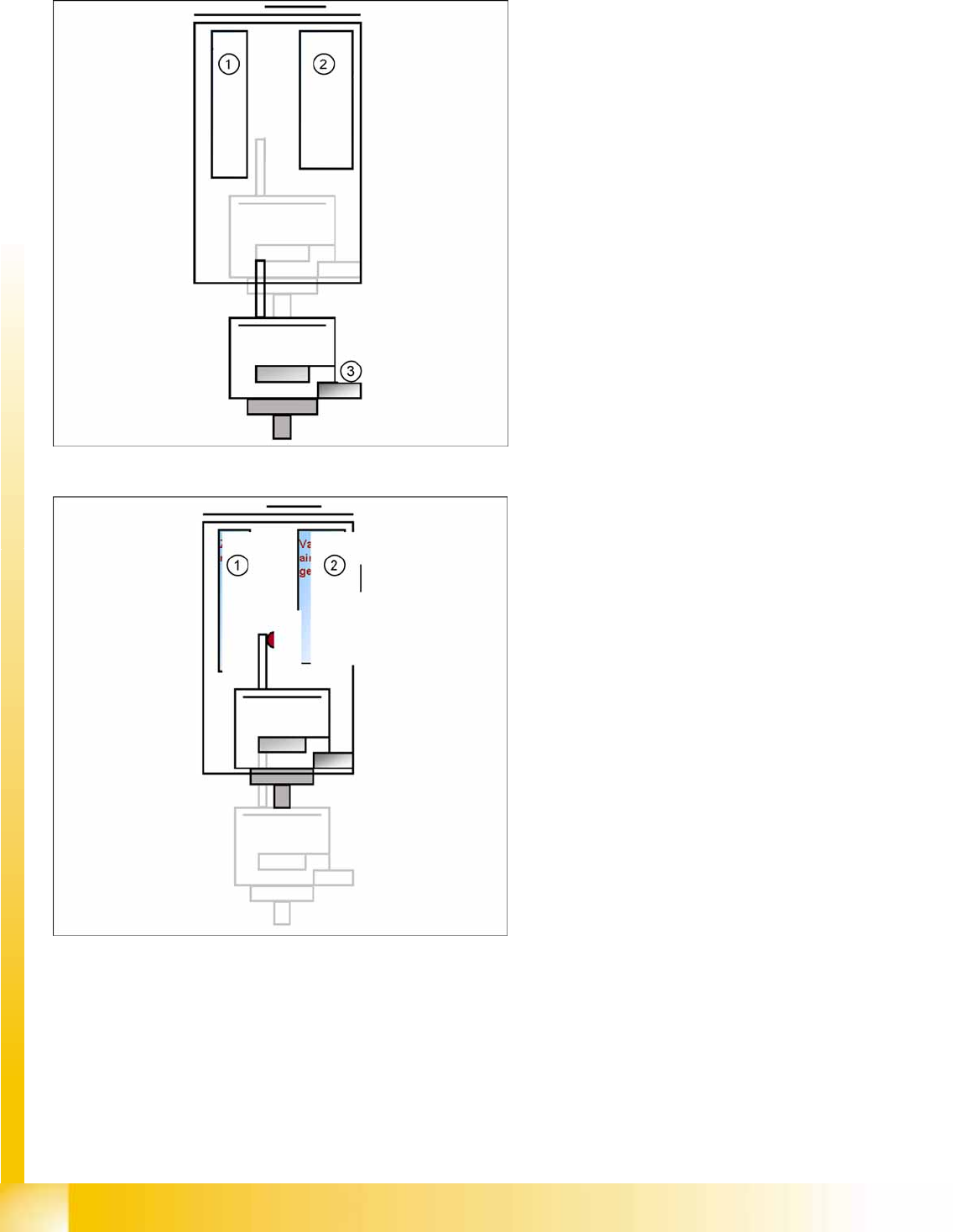
7-3: Filter for the vacuum system (TWIN segment version 03 shown as
example)
Legend
1. Filter for the vacuum system on the TWIN
Head.
The filter is mounted on the return unit and used as
an attenuator to control the vacuum. The filter, with
the relevant volume of metal hose, reduces
oscillation of the vacuum generator and
guaranteed an accurate vacuum and air blast
supply. The filter is serviced at regular intervals,
which must be adhered to (see maintenance
guide).
P&P and TWIN Heads
TWIN Head Placement Principle TWIN Head Pickup and Place Cycle
Student Guide Advanced Level 1 SIPLACE D-Series
EN 05/2007 P&P and TWIN Heads
7-5
7.2 TWIN Head Pickup and Place Cycle
7.2.1 TWIN Head Placement Principle
During the PCB transport time, the gantry waits at the theoretical fiducial position, to perform board
centering (and inkspot recognition) after PCB clamping. With the " Whispering down the machine"
option, gantry 3 only evaluates 2 fiducials.
The TWIN Head collects one component with module 1 and one component with module 2. These
components are then centered with the IC camera (FC camera) and are placed.
7.2.2 Preparations for Component Pickup (Module1)
Legend
1. Z-motor
2. D motor
PCB position recognition and ink spot
recognition is performed.
The X and Y gantry axes move to the feeder
track or pickup position.
During gantry positioning, the D-axis rotates to
the pickup angle.
Communication with component trolley -
feeder ready - opens the feeder pickup
window.
NOTE:
To achieve greater placement accuracy, the offset between the nozzle and the IC camera is
checked after a defined period, with the help of a fiducial. The fiducial is on a metal plate, which
is fixed between the stationary camera and the machine frame.
P&P and TWIN Heads
TWIN Head Pickup and Place Cycle Preparations for Component Pickup (Module1)
Student Guide Advanced Level 1 SIPLACE D-Series
P&P and TWIN Heads EN 05/2007
7-6
7.2.2.1 Component Pickup (Module 1)
Legend
1. Z-motor
2. Vacuum/air blast generator
3. Force sensor
Z-axis moves downwards with standard mode
(2 N pickup force).
On contact with the component, the force
increases to the programmed value.
When this value is reached, the end signal is
triggered and the vacuum check is activated.
Legend
1. Z-motor
2. Vacuum/air blast generator
The Z-axis moves upwards with standard
travel mode.
Communication with component trolley -
continue feeder cycle - as soon as the Z-axis
position "safety height" is reached.
When the Z-axis up end signal is emitted, the
"component on nozzle" vacuum check is
performed.
The D-axis is rotated to the placement angle
(so that only the component correction angle
needs to be rotated after centering).
Preparation for continued pickup (component
on module 2).