D-serie level 1 EN.pdf - 第124页
P&P and TWIN Heads P&P Head Main Board Preparations for Placement (Module 1 Component) S tuden t Guide Advanced Level 1 SIPLACE D-Series P&P and TWIN Heads EN 05/2007 7-10 7.3 P&P Head Main Board 7-4: P&a…
P&P and TWIN Heads
Preparations for Placement (Module 1 Component) TWIN Head Pickup and Place Cycle
Student Guide Advanced Level 1 SIPLACE D-Series
EN 05/2007 P&P and TWIN Heads
7-9
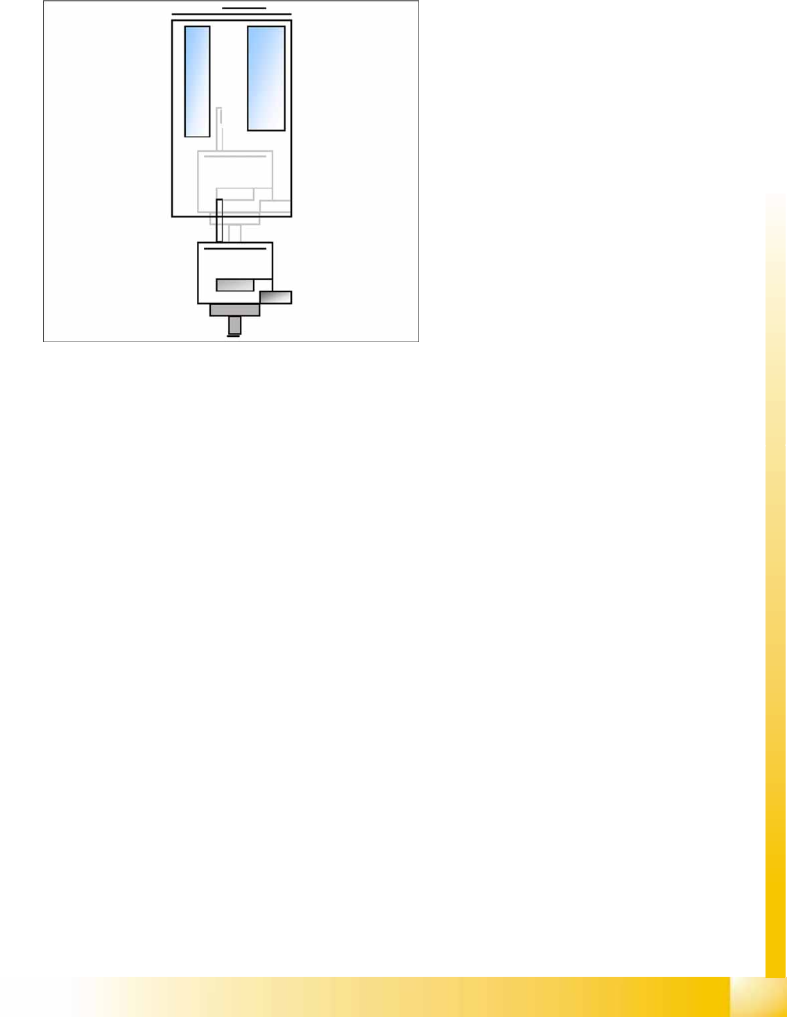
7.2.4.1 Placement (Module 1 Component)
The Z-axis moves downwards in standard
mode (2 N contact force).
The contact force increases to the
programmed level when placing the
component onto the PCB.
When this value is reached, the end signal is
triggered and the air blast control is activated.
When the air blast threshold* is reached, the
Z-axis moves upwards with the standard travel
profile.
Preparations for further placement
(component at module 2).
P&P and TWIN Heads
P&P Head Main Board Preparations for Placement (Module 1 Component)
Student Guide Advanced Level 1 SIPLACE D-Series
P&P and TWIN Heads EN 05/2007
7-10
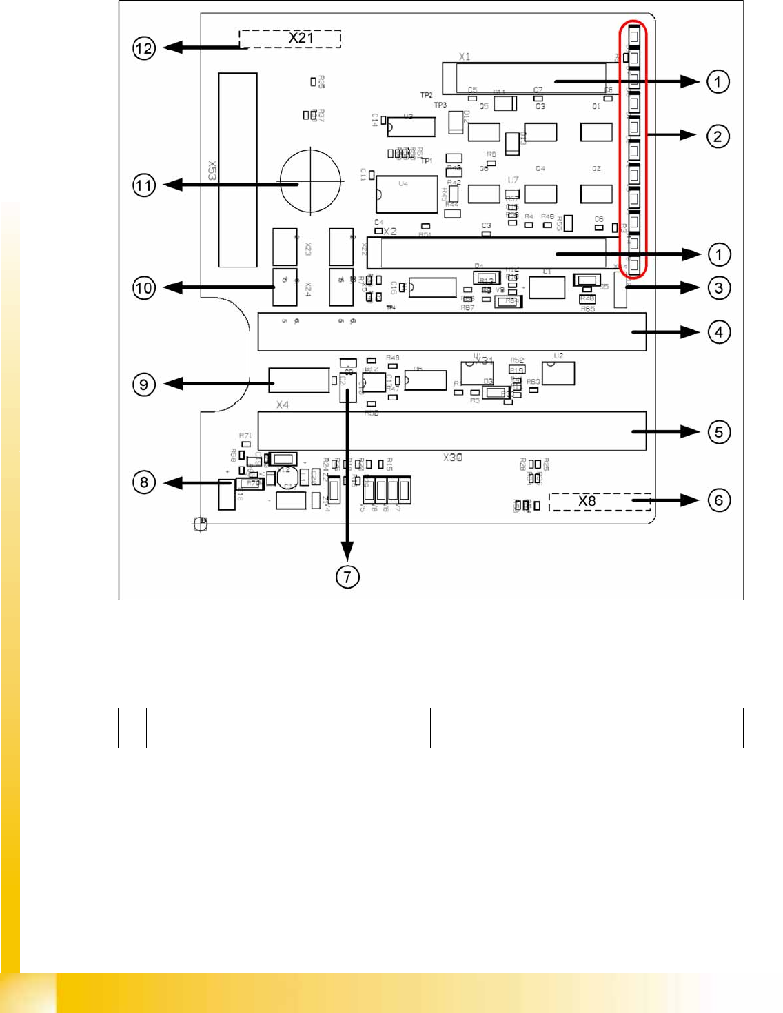
7.3 P&P Head Main Board
7-4: P&P head main board [00352833-xx]
Legend
The main board is mounted directly on the P&P head. This board is connected to the head adapter board
via two flat ribbon cables.
1 2 connectors for the 16 bit CAN Bus processor (not
used for X/D1/D3)
7 EEPROM storage the head specific data ( Head
exchange, Reference run)
P&P and TWIN Heads
Preparations for Placement (Module 1 Component) P&P Head Main Board
Student Guide Advanced Level 1 SIPLACE D-Series
EN 05/2007 P&P and TWIN Heads
7-11
To (2) LEDs (description sequence downwards):
2 LEDs (see below) 8 Power supply 15 V for the Track signals D-Axis (at
the moment deactivated via the jumper X54)
3 X54 Jumper at the moment ON with the new force
measurement board set to OFF (see LED V2/
V_SP)
9 X4 Connector track signals Z-axis
4 Connectors for flat ribbon cable of head adapter
(gantry head distributor)
10 Connector pneumatic valve (return unit)
5 Connectors for flat ribbon cable of head adapter
(gantry head distributor)
11 Hole for pneumatic pipe to the vacuum generator
6 X8: Flex-Cable (Signals: Track signals D-Axis,
Power supply Z-Axis/D-Axis, Z-Temperature and,
SPI Bus)
12 X21 connector for vacuum generator
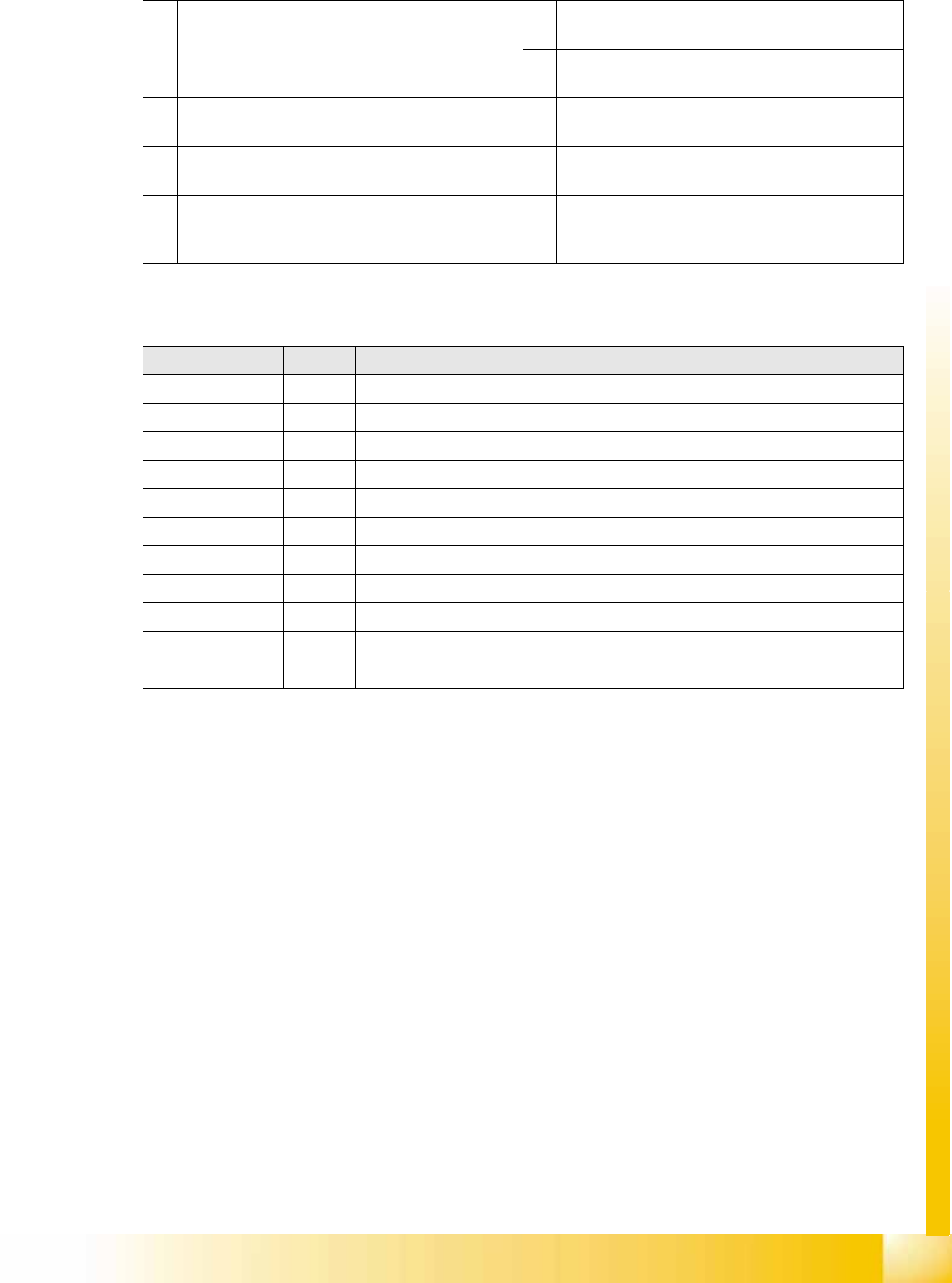
LED Color Description
D8 Green Without function (return unit)
D7 KLEMM Green Display showing that the return cylinder has been moved out and downwards.
D6 BERO - Without function (previously: proximity switch for Z-axis up)
D1 DRUCK - Without function (Z pressure)
D2 KLEMM Yellow Display showing that the return cylinder has been moved out and downwards.
V2 V_SP --
V3 15V_ Green Display showing that voltage supply is OK
V1 TEMP Green Temperature of Z-axis motor is OK
D14 ALARM Red Before initializing, CAN Bus briefly red, then off
D9 DRUCK --
D10 24V+ Green Display showing that DC voltage supply is OK.