D-serie level 1 EN.pdf - 第125页
P&P and TWIN Heads Preparations for Placement (Module 1 Component) P&P Head Main Board S tude nt Guide Advanced Level 1 SIPLACE D-Series EN 05/2007 P&P and TWIN Heads 7-1 1 To (2) LEDs (description sequence d…
P&P and TWIN Heads
P&P Head Main Board Preparations for Placement (Module 1 Component)
Student Guide Advanced Level 1 SIPLACE D-Series
P&P and TWIN Heads EN 05/2007
7-10
7.3 P&P Head Main Board
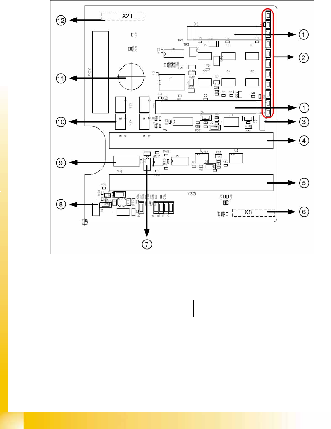
7-4: P&P head main board [00352833-xx]
Legend
The main board is mounted directly on the P&P head. This board is connected to the head adapter board
via two flat ribbon cables.
1 2 connectors for the 16 bit CAN Bus processor (not
used for X/D1/D3)
7 EEPROM storage the head specific data ( Head
exchange, Reference run)
P&P and TWIN Heads
Preparations for Placement (Module 1 Component) P&P Head Main Board
Student Guide Advanced Level 1 SIPLACE D-Series
EN 05/2007 P&P and TWIN Heads
7-11
To (2) LEDs (description sequence downwards):
2 LEDs (see below) 8 Power supply 15 V for the Track signals D-Axis (at
the moment deactivated via the jumper X54)
3 X54 Jumper at the moment ON with the new force
measurement board set to OFF (see LED V2/
V_SP)
9 X4 Connector track signals Z-axis
4 Connectors for flat ribbon cable of head adapter
(gantry head distributor)
10 Connector pneumatic valve (return unit)
5 Connectors for flat ribbon cable of head adapter
(gantry head distributor)
11 Hole for pneumatic pipe to the vacuum generator
6 X8: Flex-Cable (Signals: Track signals D-Axis,
Power supply Z-Axis/D-Axis, Z-Temperature and,
SPI Bus)
12 X21 connector for vacuum generator
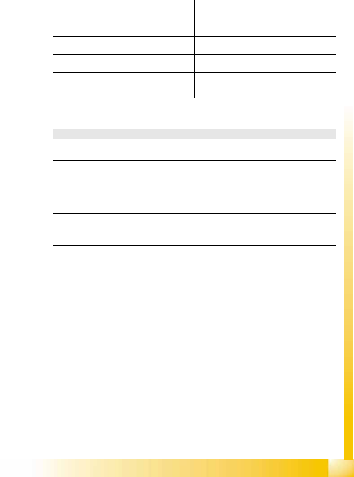
LED Color Description
D8 Green Without function (return unit)
D7 KLEMM Green Display showing that the return cylinder has been moved out and downwards.
D6 BERO - Without function (previously: proximity switch for Z-axis up)
D1 DRUCK - Without function (Z pressure)
D2 KLEMM Yellow Display showing that the return cylinder has been moved out and downwards.
V2 V_SP --
V3 15V_ Green Display showing that voltage supply is OK
V1 TEMP Green Temperature of Z-axis motor is OK
D14 ALARM Red Before initializing, CAN Bus briefly red, then off
D9 DRUCK --
D10 24V+ Green Display showing that DC voltage supply is OK.
P&P and TWIN Heads
Nozzle Changer Position and Assembly Nozzle Changer Position in D3
Student Guide Advanced Level 1 SIPLACE D-Series
P&P and TWIN Heads EN 05/2007
7-12
7.4 Nozzle Changer Position and Assembly
7.4.1 Nozzle Changer Position in D3
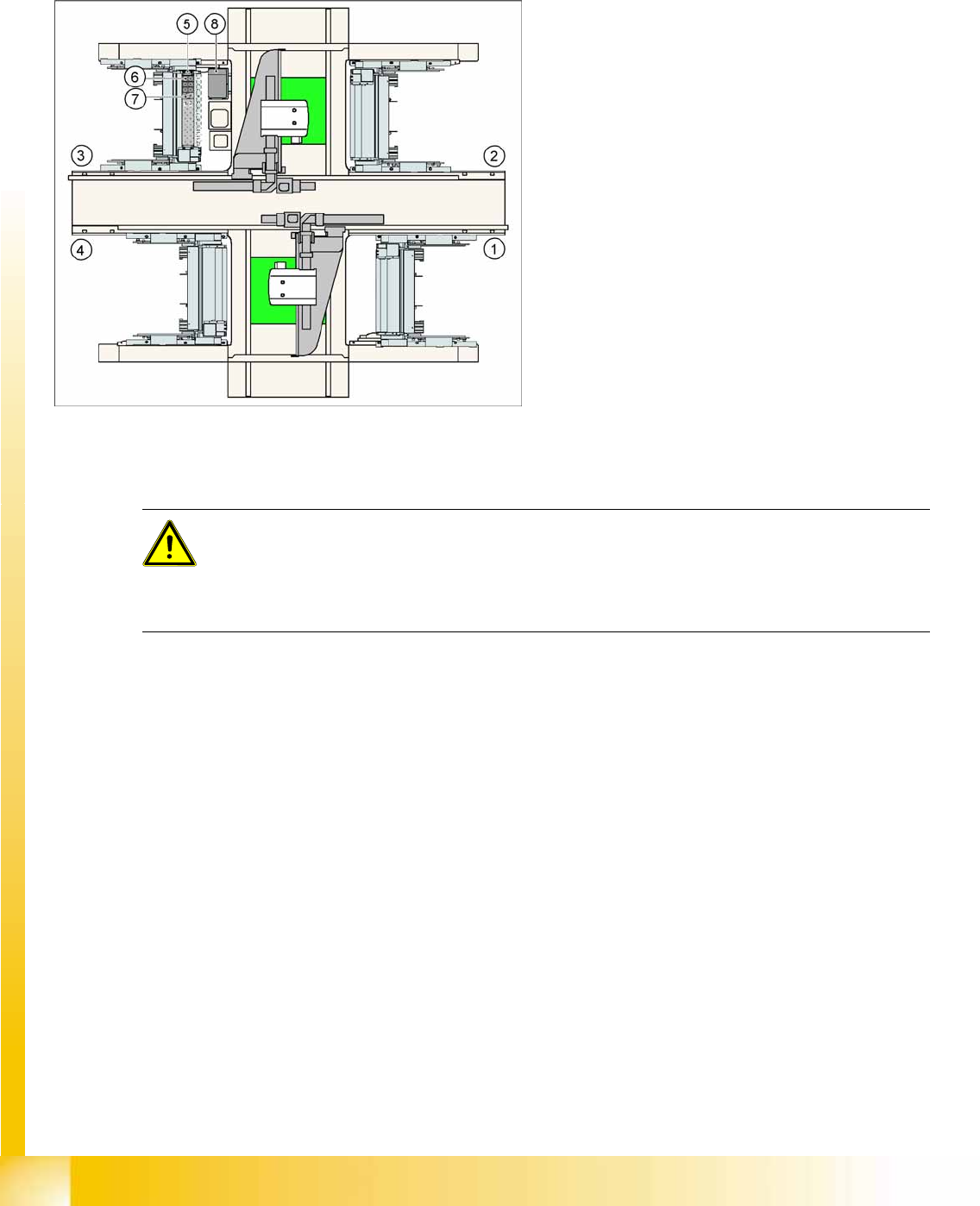
The D1 machine has a TWIN Head nozzle changer with a 2x5 magazine block arrangement.
7-5: Position of "standard nozzle changer" – sector 3 shown here (X2 shown
as example)
Legend
1. Feeder area 1
2. Feeder area 2
3. Feeder area 3
4. Feeder area 4
5. Nozzle changer garage 1
6. Standard magazine
7. Magazine for special nozzles or grippers
8. Component reject bin
ATTENTION: The magazines X/D3 magazines are therefore not compatible with D1
magazines and vice versa.
Note the change in height of the measurement fiducials at the magazines.
The magazine fixture drillings are no longer centrally aligned to the nozzle pickup, as in the case
of the X and D3 machines.