D-serie level 1 EN.pdf - 第127页
P&P and TWIN Heads Assembly of Nozzle Changer Magazines Nozzle Changer Position and Assembly S tude nt Guide Advanced Level 1 SIPLACE D-Series EN 05/2007 P&P and TWIN Heads 7-13 7.4.2 Assembly of Nozzle Changer M…
P&P and TWIN Heads
Nozzle Changer Position and Assembly Nozzle Changer Position in D3
Student Guide Advanced Level 1 SIPLACE D-Series
P&P and TWIN Heads EN 05/2007
7-12
7.4 Nozzle Changer Position and Assembly
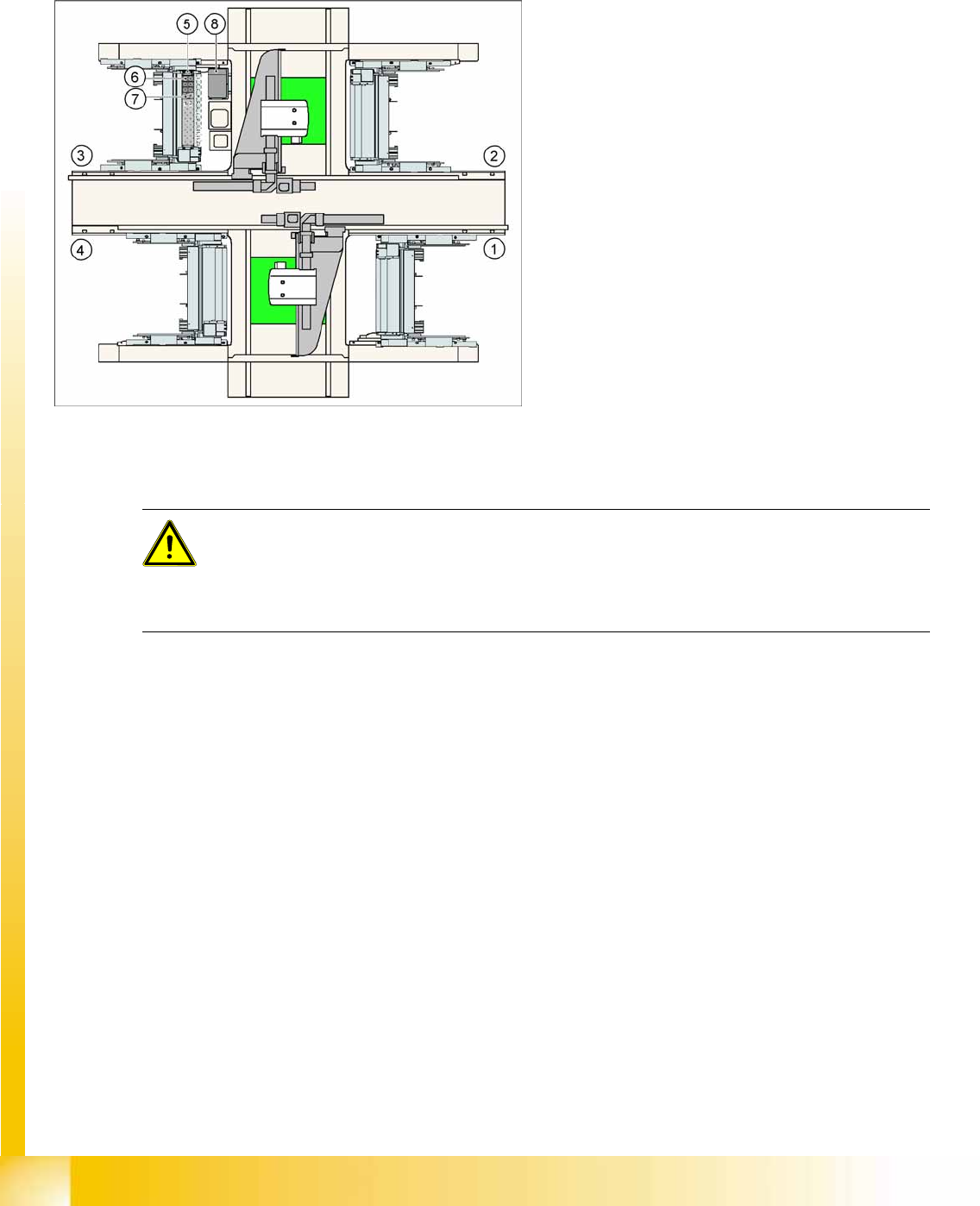
7.4.1 Nozzle Changer Position in D3
The D1 machine has a TWIN Head nozzle changer with a 2x5 magazine block arrangement.
7-5: Position of "standard nozzle changer" – sector 3 shown here (X2 shown
as example)
Legend
1. Feeder area 1
2. Feeder area 2
3. Feeder area 3
4. Feeder area 4
5. Nozzle changer garage 1
6. Standard magazine
7. Magazine for special nozzles or grippers
8. Component reject bin
ATTENTION: The magazines X/D3 magazines are therefore not compatible with D1
magazines and vice versa.
Note the change in height of the measurement fiducials at the magazines.
The magazine fixture drillings are no longer centrally aligned to the nozzle pickup, as in the case
of the X and D3 machines.
P&P and TWIN Heads
Assembly of Nozzle Changer Magazines Nozzle Changer Position and Assembly
Student Guide Advanced Level 1 SIPLACE D-Series
EN 05/2007 P&P and TWIN Heads
7-13
7.4.2 Assembly of Nozzle Changer Magazines
7.4.3 Functions
The magazine for standard nozzles has 1 positioning fiducial for position detection, while the magazine
for special nozzles/grippers has two positioning fiducials. The nozzles are fixed by balls in the garage.
They are then either locked or released for removal, depending on the direction of rotation of the DP axis.
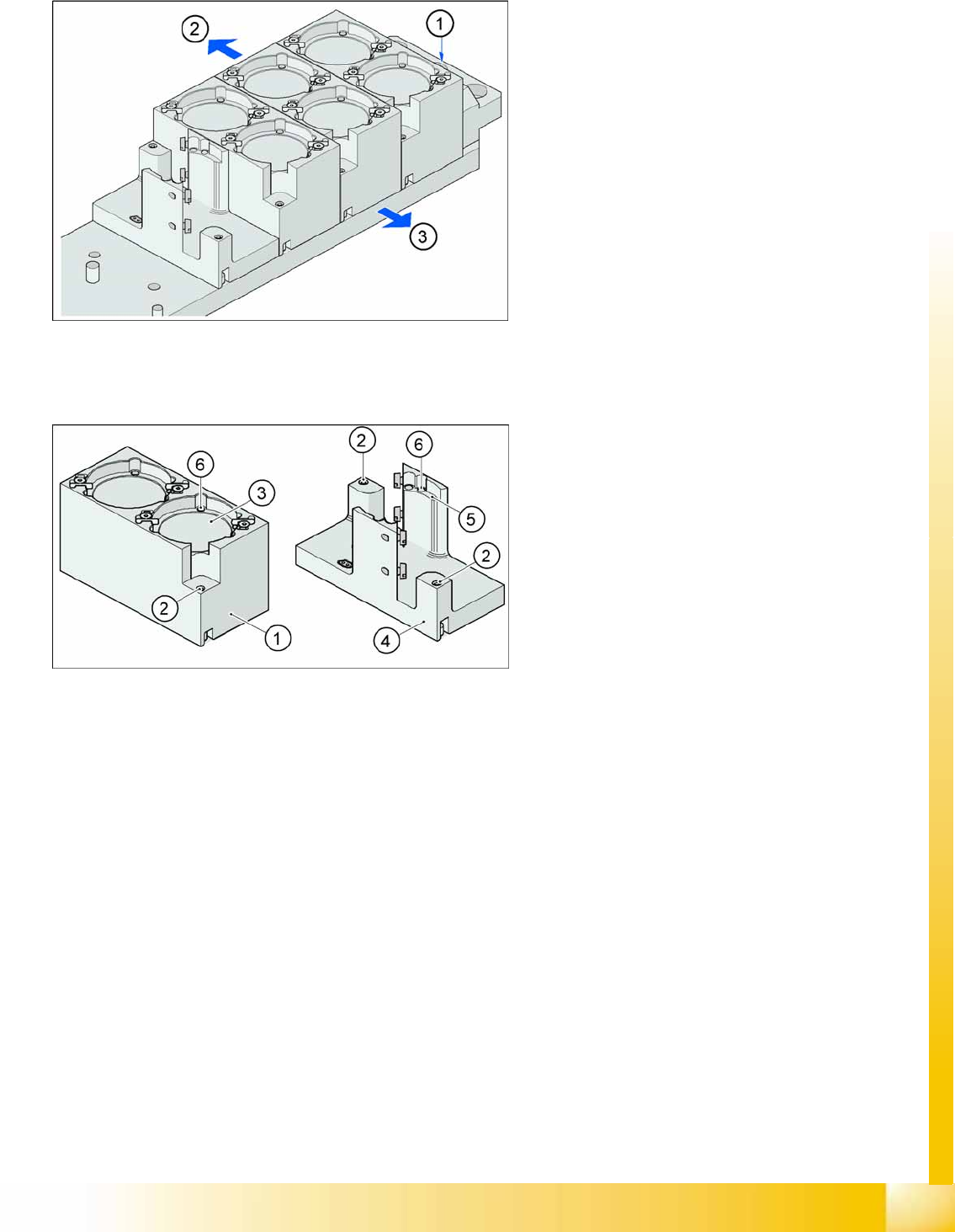
7-6: Fitting the magazines (X/D3 machine)
The nozzle changer is fixed onto the component
docking unit, together with the empty tape duct.
The magazines are seated on a common support.
They are centered with two parallel pins and fixed
in place with two countersunk screws.
Legend
1. Marking hole for nozzle changer carrier
2. Operator side (changeover table side)
3. Arrow pointing towards the PCB conveyor
Align the nozzle changer so that the marking hole
(item 1) is on the left, as viewed by the operator (at
the changeover table side).
7-7: Magazine for standard and special nozzles (HF/X/D3 machine shown
here as example)
Legend
1. Standard magazine
2. Positioning fiducial
3. Nozzle garage
4. Magazine for special nozzles
5. Nozzle garage
6. Balls for fixing the nozzles
P&P and TWIN Heads
Nozzle Changer Position and Assembly Functions
Student Guide Advanced Level 1 SIPLACE D-Series
P&P and TWIN Heads EN 05/2007
7-14
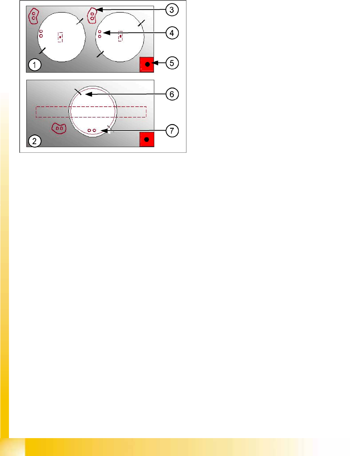
Position of the nozzle in the magazines
There is another special nozzle for the Twin head, the so-called low force nozzle. This requires a special
garage, which is not listed here.
Legend
1. Double magazine for standard nozzles (pickup
angle SW 505 = 184°)
2. Magazine for special nozzles or grippers
(pickup angle SW 505 = 275°)
3. Index pins for correct positioning of nozzles in
magazine
4. Position of nozzle with the holes for the index
pins.
5. Calibration fiducial for determining the
magazine position
6. Nozzle centering pins
7. The magazines for the special nozzles are
turned by 90° degrees.