D-serie level 1 EN.pdf - 第137页
Component Handling Optional Extension on the COT Changeover Table S tude nt Guide Advanced Level 1 SIPLACE D-Series EN 05/2007 Comp onent Handling 8-7 8.2 Changeover T able 8.2.1 Optional Extension on the COT 8 . 2 . 1 .…
Component Handling
Overview Docking and Undocking the Changeover Table
Student Guide Advanced Level 1 SIPLACE D-Series
Component Handling EN 05/2007
8-6
X Make sure that the centering bolts engage with the centering holes in the changeover table plate and
that the changeover table plate has been fully lowered.
X Close the cover flap on the pushbutton.
X Close the protective hood.
X Press the START button to start the machine.
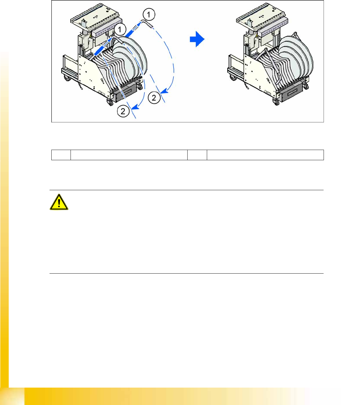
X Pull the tube (1) upwards at both handles and then swing the handles down (2).
8-3: Component trolley - swinging down the handles for pushing the trolley
Legend
Safety Instructions for Moving the Component Trolley
1 Pulling the tube upwards 2 Swinging the handles down
WARNING:
To prevent accidents, ALWAYS follow the rules listed below when you move the component
trolley.
X Always hold the handles with both hands when you want to move the component trolley.
X Remember that a component trolley with the full complement of feeder modules can tip over
sideways or forwards on gradients of 20 or more.
X Make sure that the surface on which the trolley is moved has a significantly smaller gradient.
X Be careful not to collide with obstacles. The trolley could tip forward if it is traveling fast
enough.
X Before the component trolley is moved, make sure that it has been lowered.
Component Handling
Optional Extension on the COT Changeover Table
Student Guide Advanced Level 1 SIPLACE D-Series
EN 05/2007 Component Handling
8-7
8.2 Changeover Table
8.2.1 Optional Extension on the COT
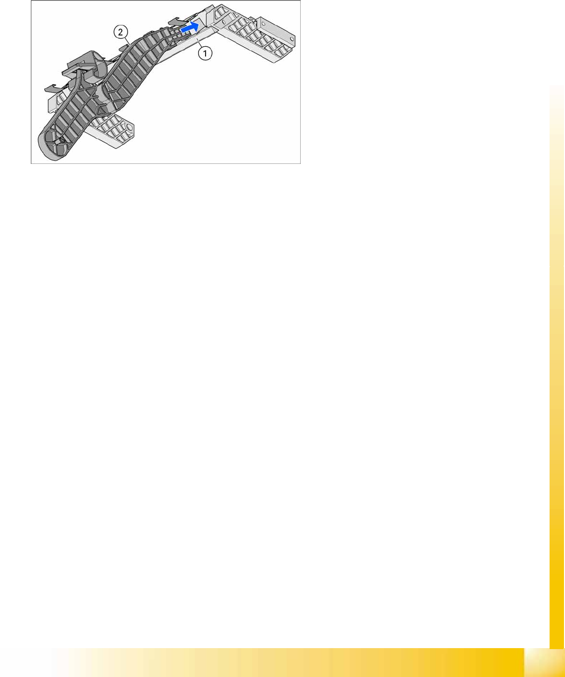
8.2.1.1 Holder for the Third Tape Reel on 3x8mm S Feeder Modules
The following parts are needed for the middle tape reel:
An adapter plate to hold the tape reel holder (1)
One tape reel holder for every two feeder modules (2).
The adapter plate is fixed with four fillister head screws to the component trolley, while the tape reel
holder is plugged into the square openings in the adapter plate.
8-4: Holder for middle tape reel in 3 x 8 mm S feeder modules, with D3 shown
as example (the diagram does not show the actual installation position in the
changeover table - the side part of the adapter plate (1) is vertical there).
Legend
1. Adapter plate
2. Tape reel holder
Feeder modules of type 3 x 8 mm-S transport
components in three feeder tracks to the pickup
position. The tape reels on the two outer tracks are
located between the divider sheets in the tape
container. The middle tape reel is located above
the two tape reels for the outer tracks.
Component Handling
Changeover Table Optional Extension on the COT
Student Guide Advanced Level 1 SIPLACE D-Series
Component Handling EN 05/2007
8-8
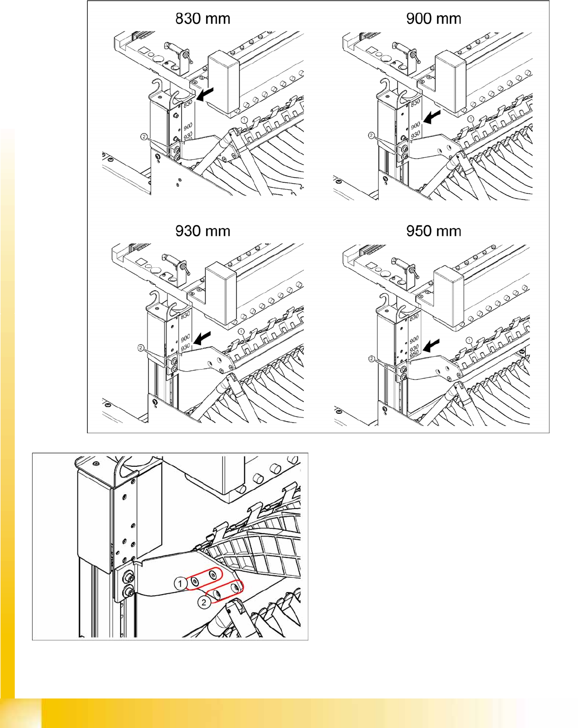
Installation position of adapter plate
Due to the various machine heights, D machines have four different installation positions for the holder
of the third tape reel (adapter plate).
Legend
1. Adapter plate installation position without
splice detection
2. Adapter plate installation position with splice
detection