D-serie level 1 EN.pdf - 第138页
Component Handling Changeover Table Optional Extension on the COT S tuden t Guide Advanced Level 1 SIPLACE D-Series Component Ha ndling EN 05/2007 8-8 Installation position of adapter plate Due to the variou s machine he…
Component Handling
Optional Extension on the COT Changeover Table
Student Guide Advanced Level 1 SIPLACE D-Series
EN 05/2007 Component Handling
8-7
8.2 Changeover Table
8.2.1 Optional Extension on the COT
8.2.1.1 Holder for the Third Tape Reel on 3x8mm S Feeder Modules
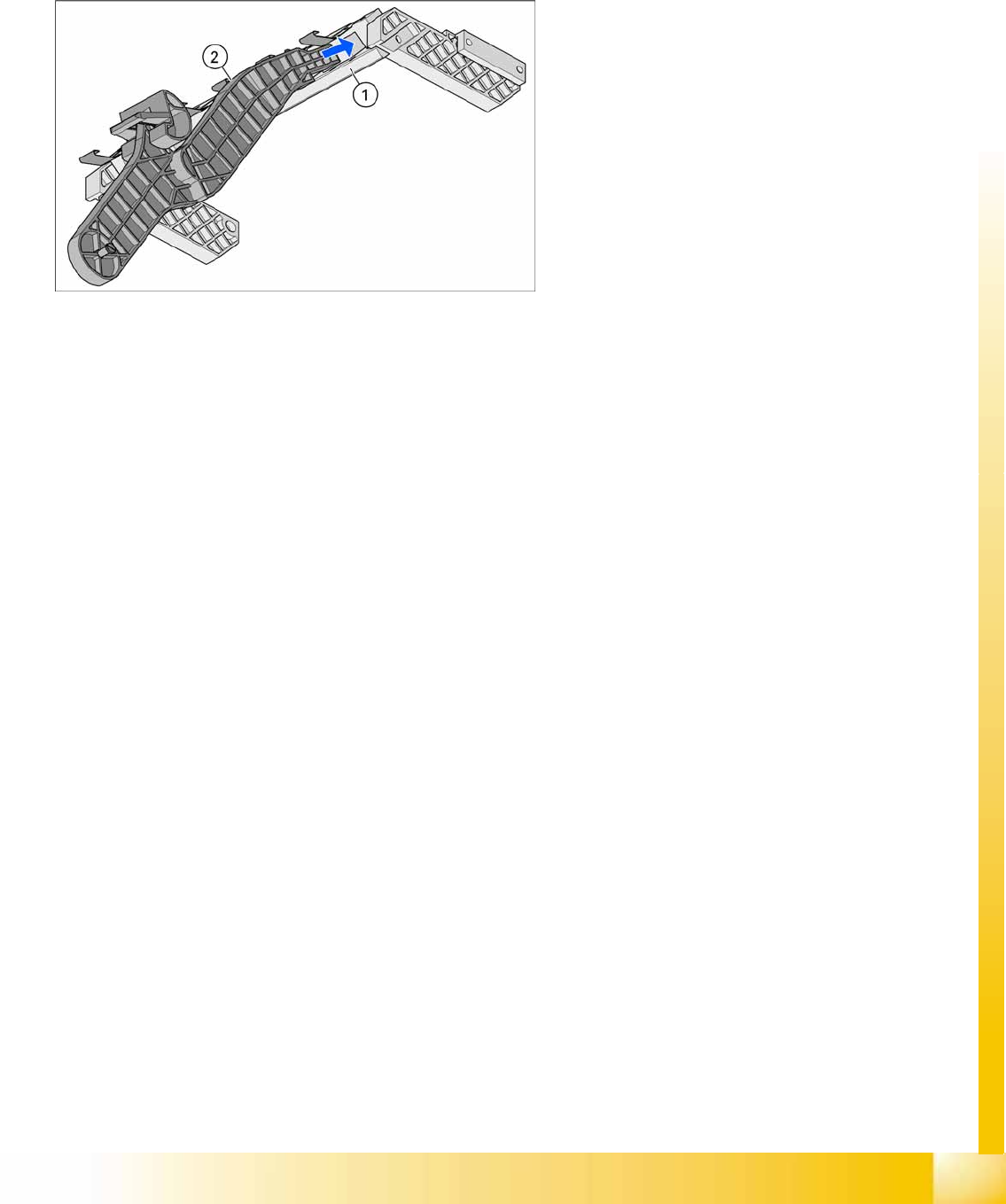
The following parts are needed for the middle tape reel:
An adapter plate to hold the tape reel holder (1)
One tape reel holder for every two feeder modules (2).
The adapter plate is fixed with four fillister head screws to the component trolley, while the tape reel
holder is plugged into the square openings in the adapter plate.
8-4: Holder for middle tape reel in 3 x 8 mm S feeder modules, with D3 shown
as example (the diagram does not show the actual installation position in the
changeover table - the side part of the adapter plate (1) is vertical there).
Legend
1. Adapter plate
2. Tape reel holder
Feeder modules of type 3 x 8 mm-S transport
components in three feeder tracks to the pickup
position. The tape reels on the two outer tracks are
located between the divider sheets in the tape
container. The middle tape reel is located above
the two tape reels for the outer tracks.
Component Handling
Changeover Table Optional Extension on the COT
Student Guide Advanced Level 1 SIPLACE D-Series
Component Handling EN 05/2007
8-8
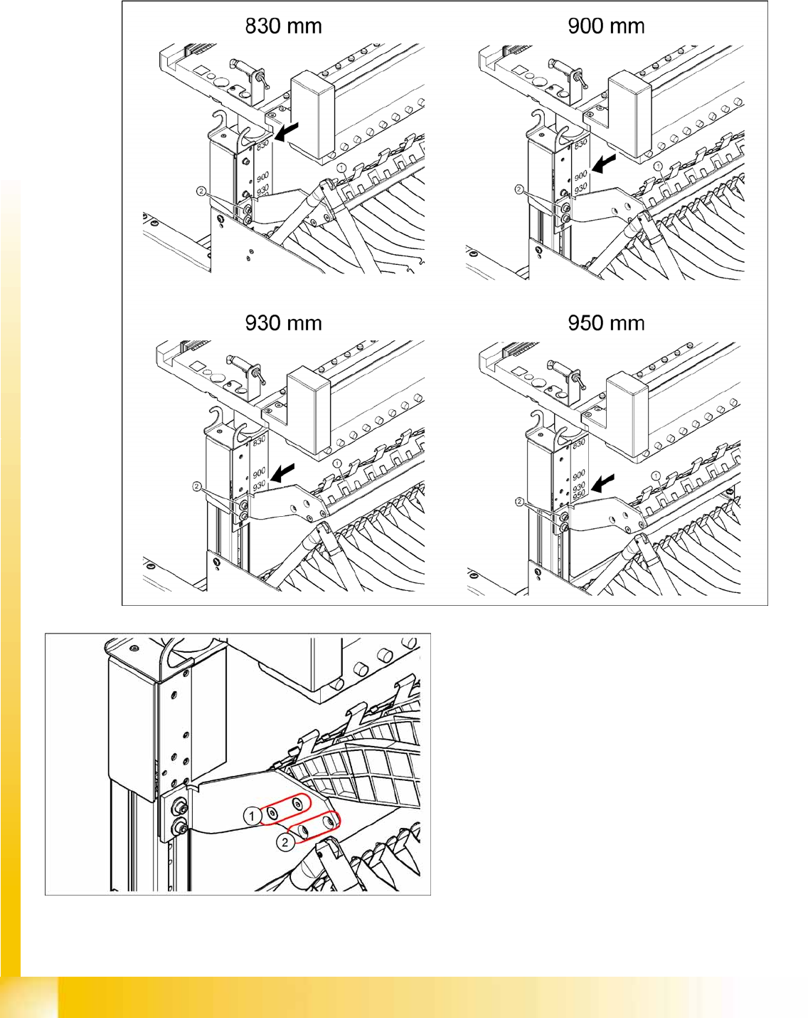
Installation position of adapter plate
Due to the various machine heights, D machines have four different installation positions for the holder
of the third tape reel (adapter plate).
Legend
1. Adapter plate installation position without
splice detection
2. Adapter plate installation position with splice
detection
Component Handling
Optional Extension on the COT Changeover Table
Student Guide Advanced Level 1 SIPLACE D-Series
EN 05/2007 Component Handling
8-9
8.2.1.2 External Power Supply
To keep the time for setup changeovers to a minimum, the component trolleys can be set up at an
external setup location. The feeder module functions and settings can also be checked there as part of
the preparations for operation. An external power supply unit is available for this purpose. The
component trolley is supplied with the required operating voltage and compressed air via a supply cable.
Technical data
Scope of delivery
Voltage supply
Power supply cables (European and US standards)
Connection cables for the three machine types D1/D2, D3 and D4
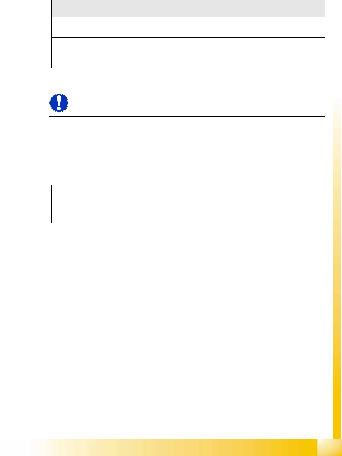
Max. tape reel size Installation position of 3rd
holder
830 mm without splice detection 43.2 mm (17") Up
830 mm with splice detection 38.1 mm (15") Down
900 mm with splice detection 48.3 mm (19") Up
900 mm without splice detection 48.3 mm (19") Down
930 / 950 mm with or without splice detection 48.3 mm (19") Either
NOTE:
For further details, refer to the installation guide for the "Adapter 3rd tape reel".
Line voltage 230 V~ ±5 %
120 V~ ±5 %
Compressed air connection max. 1.0 MPa (10 bar)
Output pressure Adjustable via valve