D-serie level 1 EN.pdf - 第141页
Component Handling Optional Extension on the COT S Feeder Modules S tude nt Guide Advanced Level 1 SIPLACE D-Series EN 05/2007 Comp onent Handling 8-1 1 8.2.1.5 Additional Communication unit for s plice detection 8.3 S F…
Component Handling
Changeover Table Optional Extension on the COT
Student Guide Advanced Level 1 SIPLACE D-Series
Component Handling EN 05/2007
8-10
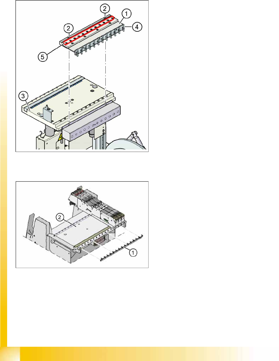
8.2.1.3 Compressed Air Supply for Bulkcase Feeders
8.2.1.4 Fixtures for S-Feeders
8-5: Compressed air supply for bulkcase feeders
Legend
1. Compressed air distributor
2. 2 x screw DIN 912, M8x20
3. Feeder table plate
4. Brackets
5. Compressed air connections for bulkcase
feeders
Bulkcase feeders require compressed air. The
optional compressed air supply for bulkcase
feeders is available for this purpose.
Installation is easy. The compressed air distributor
(1) is fixed with two screws (2) to the changeover
table (3). The compressed air distributor is then
connected to the component trolley compressed
air supply. At the back of the compressed air
distributor, there is a row of brackets (4). These fix
the bulkcase feeder modules to the changeover
table, ensuring optimum compressed air supply.
8-6: Feeder fixtures (HF shown as example)
Legend
1. Feeder fixtures
2. Changeover Table
The Feeder-Fixing is an additional mechanical
safety precaution. It prevents accidental
movement of the feeder on the changeover table.
It excludes a head crash risk with a wrong
positioned feeder. The feeder-fixation is mounted
on the front side of the changeover table. The
claws fix the feeder feet. A feeder clamp can be
installed for each of the component trolleys.

Component Handling
Optional Extension on the COT S Feeder Modules
Student Guide Advanced Level 1 SIPLACE D-Series
EN 05/2007 Component Handling
8-11
8.2.1.5 Additional Communication unit for splice detection
8.3 S Feeder Modules
8-7: Additional Communication unit for splice detection
An additional communication unit for the option
Traceability with splice detection is necessary.
The splice sensors on the communication unit
inform the station software when a new
component lot (reel) is spliced on. This sets the
new fill level for this component automatically.
Legend
1. The additional communication unit is screwed
into place, together with the changeover table
communication unit.
NOTE: SCMC 604
SC/MC 604 alters the feeder function for the components.
The changeover table controller activates the conveyor process just before access to the feeder
track is needed. This has the following benefits:
X Components are not left exposed and the feeders can be removed from the machine without
component loss.
X Should the cutting procedure tug slightly at the empty tape, this will no longer cause lighter
components to jump because the components remain covered until just before pickup.
NOTE:
Please note that the changeover table surfaces must always be kept clean and free of
components before the feeder modules are inserted.
NOTE:
Please note that the changeover table contact surfaces must always be kept clean and free of
components before the changeover tables are inserted.
This helps prevent pickup errors and unnecessary calibration runs.

Component Handling
Room for Your Sketches and Notes Optional Extension on the COT
Student Guide Advanced Level 1 SIPLACE D-Series
Component Handling EN 05/2007
8-12
8.4 Room for Your Sketches and Notes