D-serie level 1 EN.pdf - 第153页
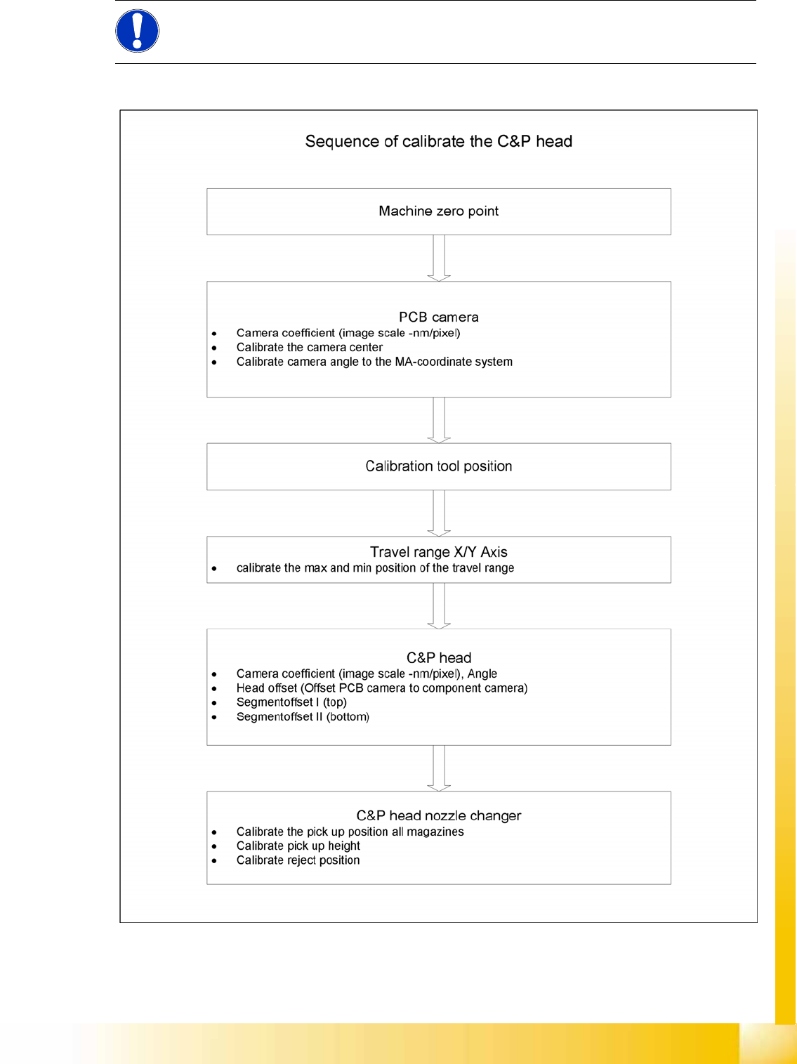
SITEST C&P Head Calibration S tude nt Guide Advanced Level 1 SIPLACE D-Series EN 05/2007 SITEST 9-9 9.2.3 C&P Head 9-3: Sequence of C&P head calibration NOTE: When configuring the C&P12 (only), you can al…
SITEST
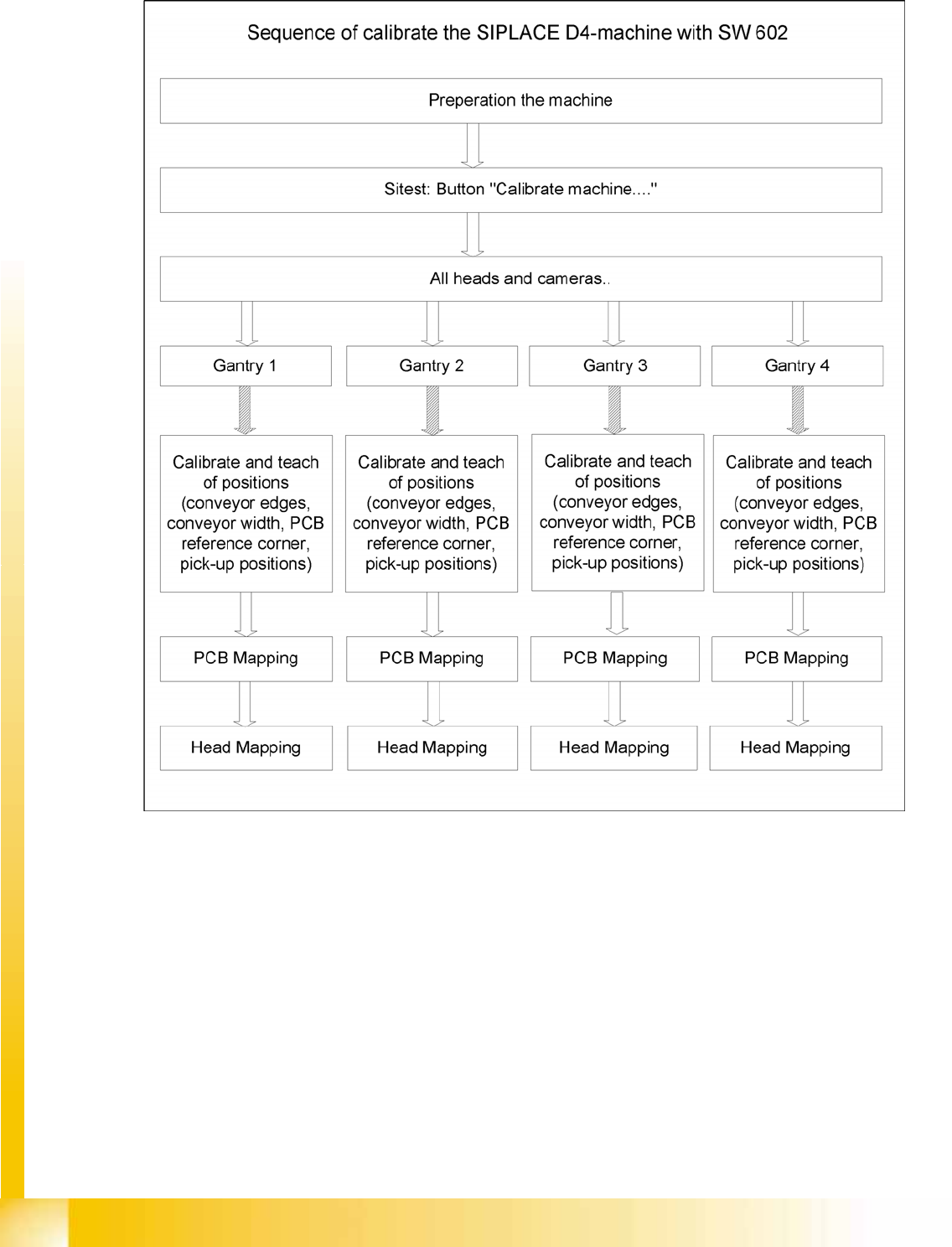
Calibration Calibration - General Sequence
Student Guide Advanced Level 1 SIPLACE D-Series
SITEST EN 05/2007
9-8
9.2.1 Calibration - General Sequence
9-2: General sequence to calibrate the machine
9.2.2 Requirements for Calibration of Nozzle Changers in the SIPLACE D Machines
X Start SITEST.
X by selecting the menu items
MAIN VIEW
,
Overall reference run
, to start the reference run for all
gantries and heads.
X Configure the nozzle changer and check the component levels.
Precondition for calibrate the nozzle changer
Each magazine in the NC must be configured with a nozzle type.
There should be no nozzle at segment 1 .
Each magazine must at least have a nozzle present and configured (1) in garage 1 .
SITEST
C&P Head Calibration
Student Guide Advanced Level 1 SIPLACE D-Series
EN 05/2007 SITEST
9-9
9.2.3 C&P Head
9-3: Sequence of C&P head calibration
NOTE:
When configuring the C&P12 (only), you can also set all magazines to "empty" and the head to
"full".
SITEST
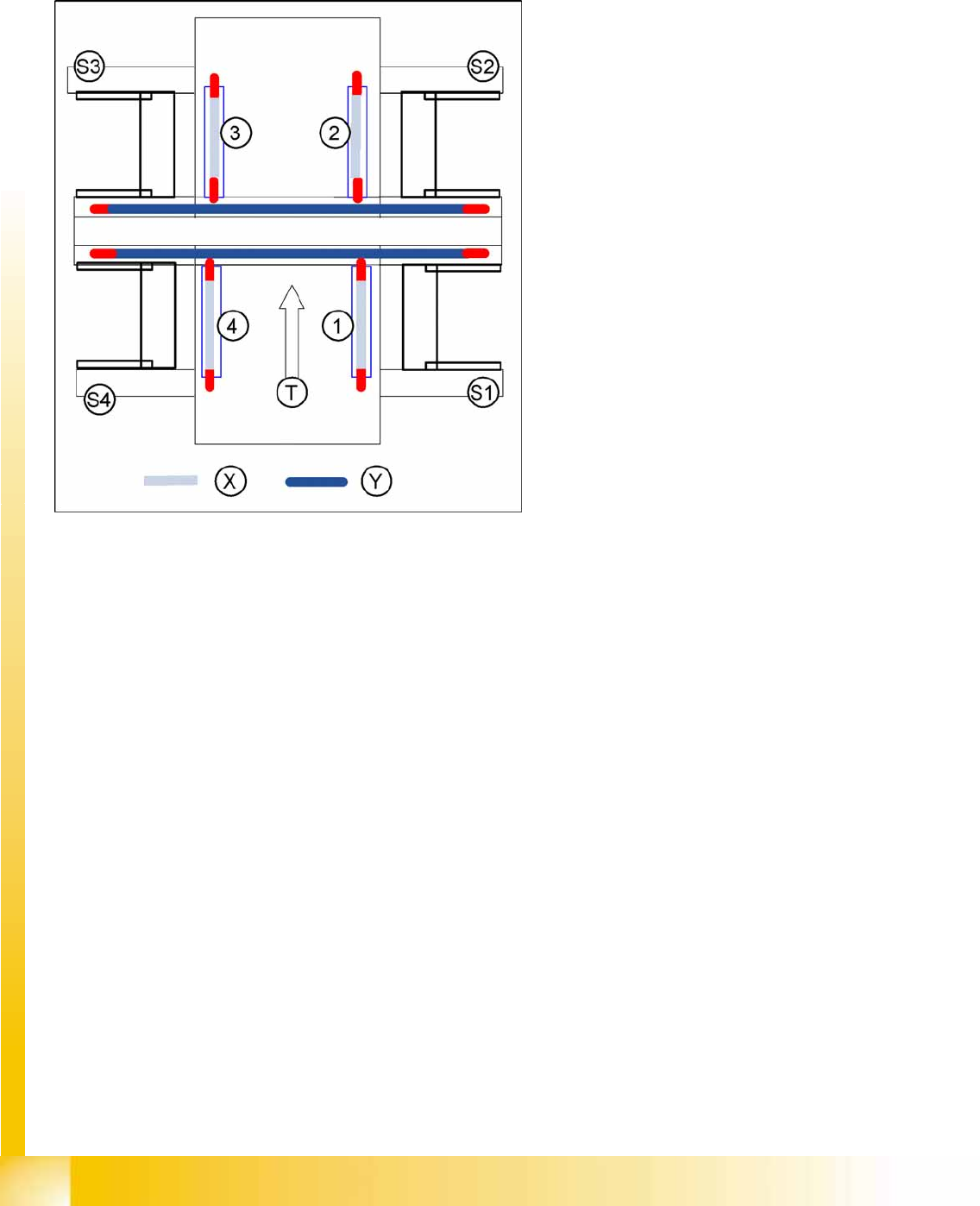
Calibration Basics Travel Range
Student Guide Advanced Level 1 SIPLACE D-Series
SITEST EN 05/2007
9-10
9.3 Calibration Basics
9.3.1 Travel Range
9.3.1.1 Position of Calibration Tool
Calibrate the X and Y pick up position of the calibration tool.
X gantry axis:
The X gantry axis moves to the zero pulse, to
calibrate the travel range and then moves on
to the HW end stoppers (limit switch). The
respective gantry axis position is recorded
there.
The maximum hardware travel range is set 1.5
mm before the bumper. The software travel
range value is 0.5 mm before that.
Y gantry axis:
The Y gantry axis moves to the zero pulse, to
calibrate the travel range and then moves on
to the outer HW end stoppers on the left or
right (limit switch). The respective gantry axis
position is recorded there.
The maximum hardware travel range is set 1.5
mm before this position. The software travel
range value is 1.5 mm before that.
In the case of the Y axes, only the outer HW
end stoppers are approached in each case.
The other end position of the travel path is
calculated. This gives a travel range distance
to the other gantry of about 35 mm.
Legend
1-4:Gantry 1-4
S1 - S4:Sector 1-4
X:Travel range X
Y:Travel range Y
T:Transport direction