D-serie level 1 EN.pdf - 第16页
Operational Safety Safety Instructions for Moving the Component Trolley Positi on of Controls for Docking and Un docking the Component Trolley S tuden t Guide Advanced Level 1 SIPLACE D-Series Operational Safety EN 05/20…
Operational Safety
Safety of Operators and Other Persons Safety Instructions
Student Guide Advanced Level 1 SIPLACE D-Series
EN 05/2007 Operational Safety
2-1
2 Operational Safety
2.1 Safety Instructions
Any staff working on the machine must be familiar with the safety instructions in this user manual and
observe these at all times.
The following safety instructions are an excerpt from Chapter 1 "Operational Safety" of the SIPLACE
user manual.
2.1.1 Safety of Operators and Other Persons
Machine operators must only carry out work for which they have been adequately trained and with which
they are totally familiar.
2.1.2 Safety of Plants and Equipment
Never make changes, however minor, unless you are totally aware of the effect they will have on the
overall functioning of the system.
The stations must always be set up, retooled and maintained by appropriately trained personnel.
Only use original spare arts and authorized accessories from Siemens AG. The use of other parts
will affect safety and will invalidate the liability for any consequential damage.
Do not make modifications to the safety equipment. Never bridge protective switches or remove
protective devices.
2.2 Warning Labels
WARNING:
The system is electrically driven. When electrical devices are in use, certain parts carry
dangerous voltage levels.
X Switch off at the main switch and disconnect the placement system from the power supply
before carrying out any work on live components.
X Lock the machine.
X There is a risk of death, severe injury and/or considerable damage to equipment if these
instructions are not followed.
ATTENTION: Observe all warning labels!
Observe the warning labels during the training course! These are explained in detail in the
operating manual – warning signs chapter of the relevant machine.
Operational Safety
Safety Instructions for Moving the Component Trolley Position of Controls for Docking and Undocking the Component Trolley
Student Guide Advanced Level 1 SIPLACE D-Series
Operational Safety EN 05/2007
2-2
2.3 Safety Instructions for Moving the Component Trolley
X Always hold the handles with both hands when you want to move the component trolley.
X Remember that a component trolley with the full complement of feeder modules can tip over
sideways or forward on gradients of 20 or more.
X Make sure that the surface on which the trolley is moved has a significantly smaller gradient.
X Be careful not to collide with obstacles. The trolley could tip forward if it is traveling fast enough.
X When it is outside the machine, always lower the component trolley.
X Connect the trolley with the plug provided before inserting it into the machine. Lift the trolley and
move it into the machine.
X In the machine, the pneumatic switch must always be down , to ensure that the table is not stopped
in an intermediate position.
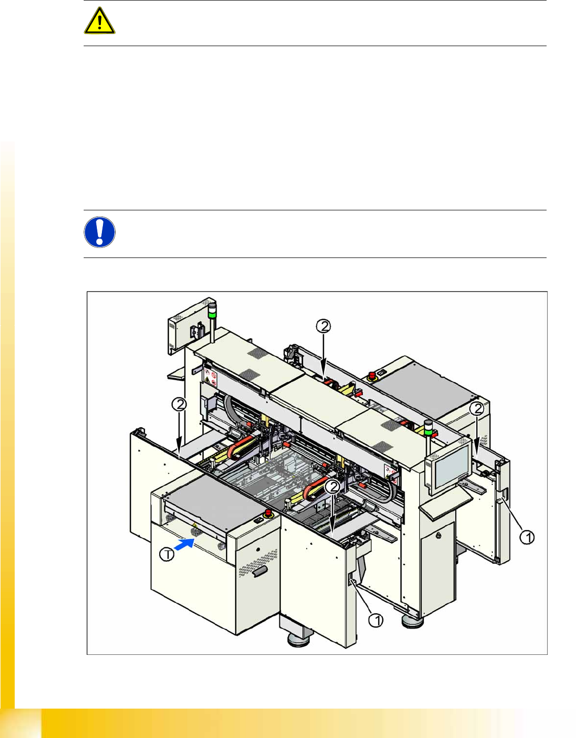
2.3.1 Position of Controls for Docking and Undocking the Component Trolley
2-1: Position of pushbuttons on the component trolley
WARNING:
To prevent accidents, ALWAYS follow the rules listed below when you move the component
trolley.
NOTE: Optional equipment
Changeover tables in the D4/D2/D1 series can be equipped with an optional device to prevent
the table being raised or lowered if it is not connected to the machine.
Operational Safety
Switches and Buttons on the Placement Machine Safety Equipment
Student Guide Advanced Level 1 SIPLACE D-Series
EN 05/2007 Operational Safety
2-3
Legend
1. Connection for component trolley
2. Pushbutton for raising the changeover tables, with feeder cover plate flap above
T = PCB direction of transport
The switch used to lower the changeover tables is located at the left, rear of the changeover table. This
switch will only be accessible when the feeder cover plate is open.
2.4 Safety Equipment
2.4.1 Switches and Buttons on the Placement Machine
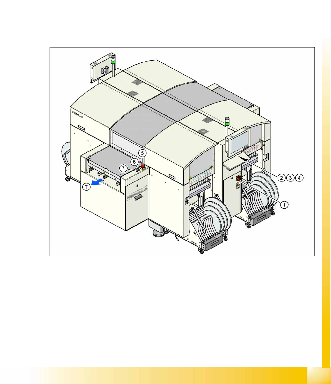
2.4.1.1 Position of Switches and Buttons on the Placement Machine
2-2: Position of switches and buttons - View of the PCB output side (D4)
Legend
1. Main switch
2. Stop button (black) on the operator panel on the power supply side
3. Start button (white) on the operator panel on the power supply side
4. Component counter on the operator panel on the power supply side
5. Emergency stop button on the output side
6. Start button (white) on the output side
7. Stop button (white) on the output side
T = PCB direction of transport