D-serie level 1 EN.pdf - 第167页
SIPLACE Vision General Optical Fiducial Models S tude nt Guide Advanced Level 1 SIPLACE D-Series EN 05/2007 SIPLACE V i sion 10-1 10 SIPLACE V ision 10.1 Optical Fiducial Models Digital PCB camera with multicolor illumin…

SITEST
Room for Your Sketches and Notes New Functions in SITEST
Student Guide Advanced Level 1 SIPLACE D-Series
SITEST EN 05/2007
9-22

SIPLACE Vision
General Optical Fiducial Models
Student Guide Advanced Level 1 SIPLACE D-Series
EN 05/2007 SIPLACE Vision
10-1
10 SIPLACE Vision
10.1 Optical Fiducial Models
Digital PCB camera with multicolor illumination
10.1.1 General
This digital version of the multicolor PCB camera SST 24 differs from the analog multicolor PCB camera
SST 18.
Parameter PCB camera 24 PCB camera 34
For machine X2; X3; X4 HS-D
SST 24 34
Resolution 11.7 µm/pixels
Field of view 5.7 x 5.7 mm
(695x494 pixels/used: 494x494 pixels)
Min. fiducial
size
Circle, square, rectangle 0.25 x 0.25 mm / and
their rings 0.3 x 0.3 mm /
Cross 0.3 x 0.3 mm / double cross, diamond 0.5
x 0.5 mm (= 0.25 mm edge length for diamond or
0.35 mm height/width).min. line thickness is 0.1
mm is each case.
Max. fiducial
size
3 x 3 mm
Illumination
types/colors
White, diffuse (flat)
White, steep
IR diffuse (flat)
IR steep
Blue
SIPLACE Vision
Optical Fiducial Models Fiducial Shapes For PCB Position and Placement Position Recognition
Student Guide Advanced Level 1 SIPLACE D-Series
SIPLACE Vision EN 05/2007
10-2
10.1.1.1 Illumination Type for Fiducials with Standard Camera SST38
The following recommendations apply for the choice of fiducial material:
When teaching the fiducial shapes, the complete programmed PCB is defined, including all fiducial
coordinates! At the station, Single Functions is selected to move the first PCB into position for teaching
the fiducials and inkspots. All required fiducials are taught and can then be tested with all cameras, using
the Test all fiducials function. Production then starts with the next PCB.
10.1.1.2 Fiducial Arrangement on the PCB
If the fiducials are only arranged in one row on the PCB, this enables you to determine the PCB position
and the PCB angle.Since two fiducials are sufficient for this, SIPLACE Pro only transmits two fiducial
positions.
The PCB fiducial positions transmitted to the station;
The following can be calculated: PCB position, PCB angle and PCB length offset.
The PCB fiducial positions transmitted to the station;
The following can be calculated: PCB position, PCB angle plus PCB length and width offset.
10.1.1.3 Importing Fiducials
All fiducials which are defined as such in ICOS need to be retaught for SIPLACE Vision.
In this case, there is no need to consider a mutual influencing of the two optical recognition systems, as
sensor-specific saving of the parameters is possible (5 SST, 24 SST,…).
Special case: SIPLACE Vision accepts double crosses as a synthetic fiducial type; ICOS systems define
this type as 2D pattern; it is therefore not possible to import this fiducial type.
10.1.2 Fiducial Shapes For PCB Position and Placement Position Recognition
The following 7 (or 9) fiducial shapes can be taught as synthetic fiducials:
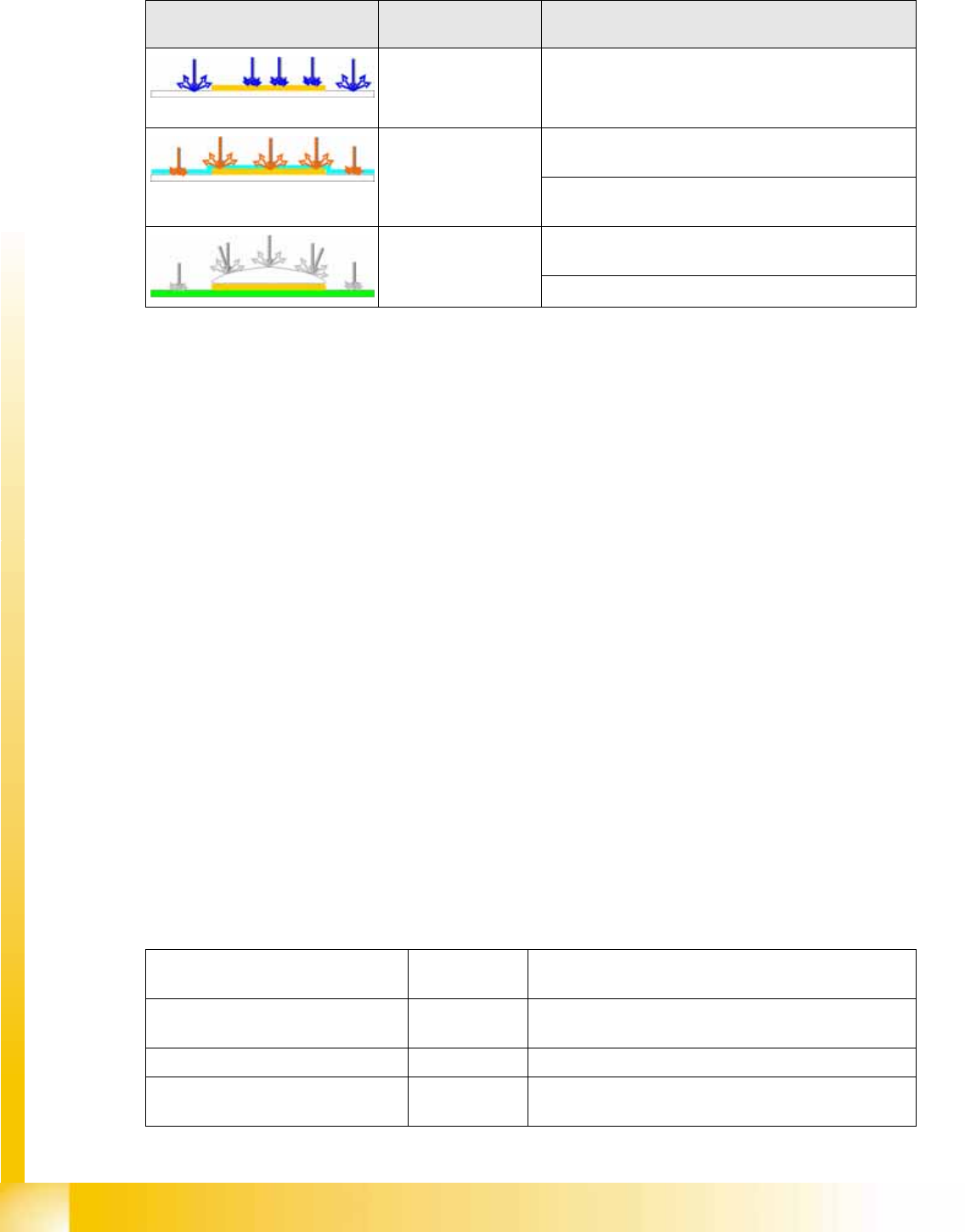
Example Illumination type/
illumination color
PCB material
e.g. gold on ceramic
Blue for recognition of gold or silver-colored fiducials on
white material (ceramic).
Red, diffuse to penetrate the coating on matt fiducial surfaces, so
that the PCB fiducial can be recognized.
for recognition of matt fiducials on any PCB surface
and any PCB material.
Red, steep combined
with diffuse
for recognition of fiducials under the coating of
reflective fiducial surfaces (e.g. glass plates).
For reliable recognition of reflective fiducial surfaces.
Fiducial type
(name in fiducial list)
Minimum size To be taught/comments
Cross; Double cross; 0.3 mm long,
0.1 mm thick
Shape, dimensions and line thickness; can be shown as
light or dark
Circle D 0,25 Shape, dimensions; can be shown as light or dark
Circular ring D 0.3 mm,
0.1 mm thick
Shape, dimensions and line thickness; can be shown as
light or dark