D-serie level 1 EN.pdf - 第17页
Operational Safety Switches and Buttons on the Placement Machine Safety Equipment S tude nt Guide Advanced Level 1 SIPLACE D-Series EN 05/2007 Operational Safety 2-3 Legend 1. Connection for component tro lley 2. Pushbut…
Operational Safety
Safety Instructions for Moving the Component Trolley Position of Controls for Docking and Undocking the Component Trolley
Student Guide Advanced Level 1 SIPLACE D-Series
Operational Safety EN 05/2007
2-2
2.3 Safety Instructions for Moving the Component Trolley
X Always hold the handles with both hands when you want to move the component trolley.
X Remember that a component trolley with the full complement of feeder modules can tip over
sideways or forward on gradients of 20 or more.
X Make sure that the surface on which the trolley is moved has a significantly smaller gradient.
X Be careful not to collide with obstacles. The trolley could tip forward if it is traveling fast enough.
X When it is outside the machine, always lower the component trolley.
X Connect the trolley with the plug provided before inserting it into the machine. Lift the trolley and
move it into the machine.
X In the machine, the pneumatic switch must always be down , to ensure that the table is not stopped
in an intermediate position.
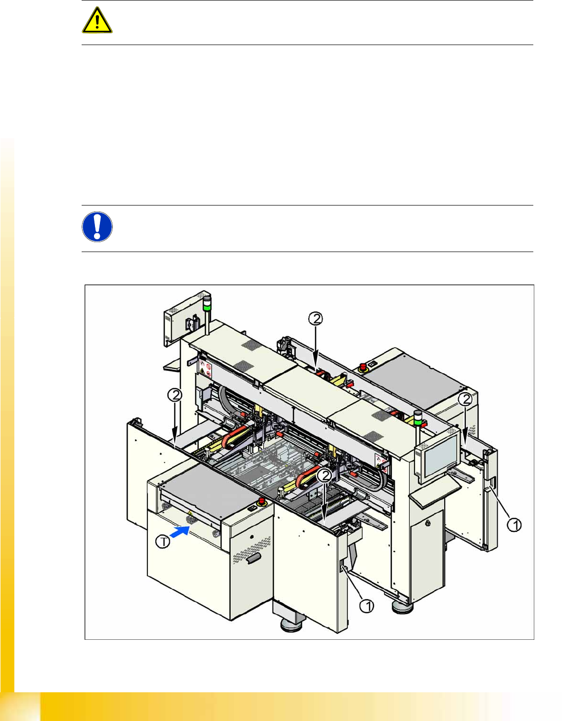
2.3.1 Position of Controls for Docking and Undocking the Component Trolley
2-1: Position of pushbuttons on the component trolley
WARNING:
To prevent accidents, ALWAYS follow the rules listed below when you move the component
trolley.
NOTE: Optional equipment
Changeover tables in the D4/D2/D1 series can be equipped with an optional device to prevent
the table being raised or lowered if it is not connected to the machine.
Operational Safety
Switches and Buttons on the Placement Machine Safety Equipment
Student Guide Advanced Level 1 SIPLACE D-Series
EN 05/2007 Operational Safety
2-3
Legend
1. Connection for component trolley
2. Pushbutton for raising the changeover tables, with feeder cover plate flap above
T = PCB direction of transport
The switch used to lower the changeover tables is located at the left, rear of the changeover table. This
switch will only be accessible when the feeder cover plate is open.
2.4 Safety Equipment
2.4.1 Switches and Buttons on the Placement Machine
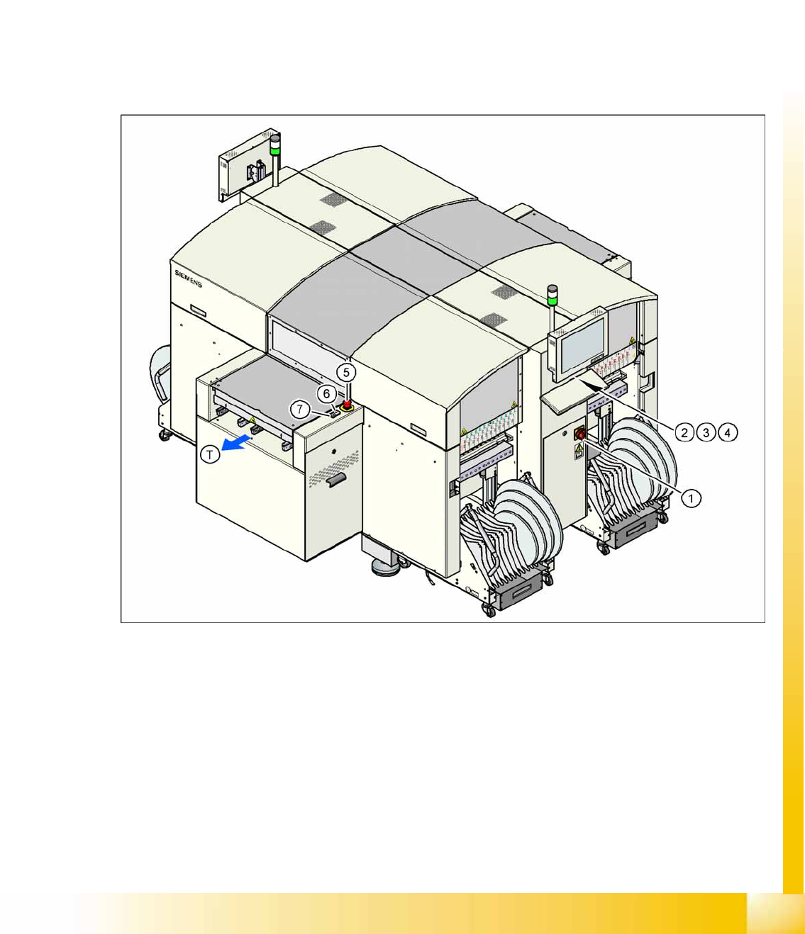
2.4.1.1 Position of Switches and Buttons on the Placement Machine
2-2: Position of switches and buttons - View of the PCB output side (D4)
Legend
1. Main switch
2. Stop button (black) on the operator panel on the power supply side
3. Start button (white) on the operator panel on the power supply side
4. Component counter on the operator panel on the power supply side
5. Emergency stop button on the output side
6. Start button (white) on the output side
7. Stop button (white) on the output side
T = PCB direction of transport
Operational Safety
Safety Equipment Switches and Buttons on the Placement Machine
Student Guide Advanced Level 1 SIPLACE D-Series
Operational Safety EN 05/2007
2-4
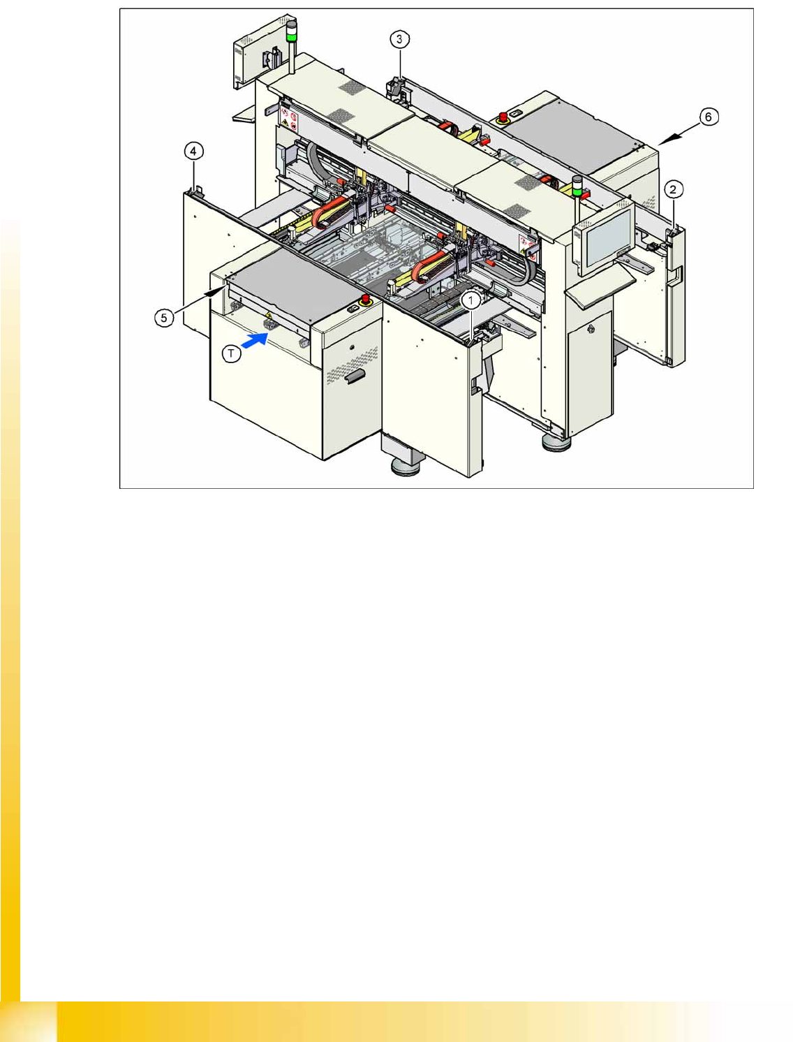
2.4.1.2 Position of Protective Switches on the Placement Machine
2-3: Position of protective switches on the placement machine (example of D4 shown)
Legend
1. Protective cover switch, location 1
2. Protective cover switch, location 2
3. Protective cover switch, location 3
4. Protective cover switch, location 4
5. Protective switch for the cover flap on the PCB conveyor input side
6. Protective switch for the cover flap on the PCB conveyor output side
T = PCB direction of transport