D-serie level 1 EN.pdf - 第173页
SIPLACE Vision Inkspot Recognition Optical Fiducia l Models S tude nt Guide Advanced Level 1 SIPLACE D-Series EN 05/2007 SIPLACE V i sion 10-7 10.1.3 Inkspo t Recognition There are va rious programm ing options for inks …
SIPLACE Vision
Optical Fiducial Models Fiducial Shapes For PCB Position and Placement Position Recognition
Student Guide Advanced Level 1 SIPLACE D-Series
SIPLACE Vision EN 05/2007
10-6
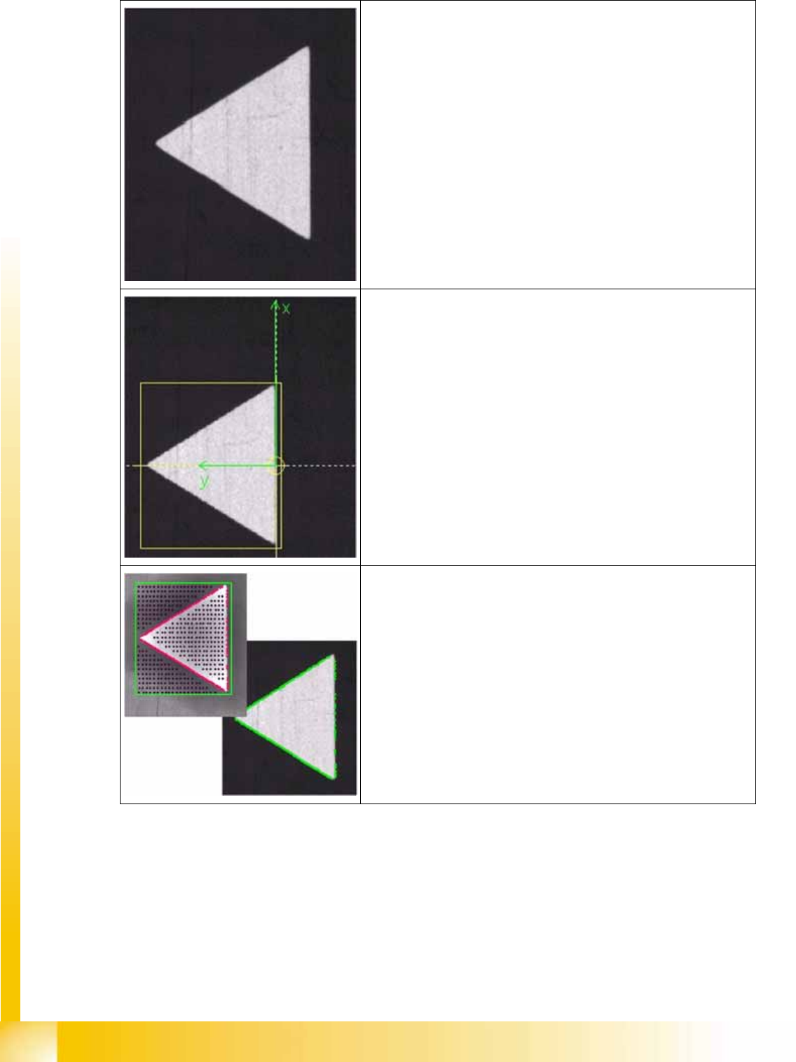
Camera image of triangular fiducial
Determined reference point
The reference point of a fiducial determines the placement positions.
It is therefore important to set it as exactly as possible onto the
positions based on the placement coordinates.
The automatic procedure has selected the point with the greatest
change in brightness, in this case.
Taught pattern:
Starting from the reference point, the system learns the shape of the
pattern and saves this diagram of the outline as the teach image.
(bottom right shows position measurement with taught outline)
SIPLACE Vision
Inkspot Recognition Optical Fiducial Models
Student Guide Advanced Level 1 SIPLACE D-Series
EN 05/2007 SIPLACE Vision
10-7
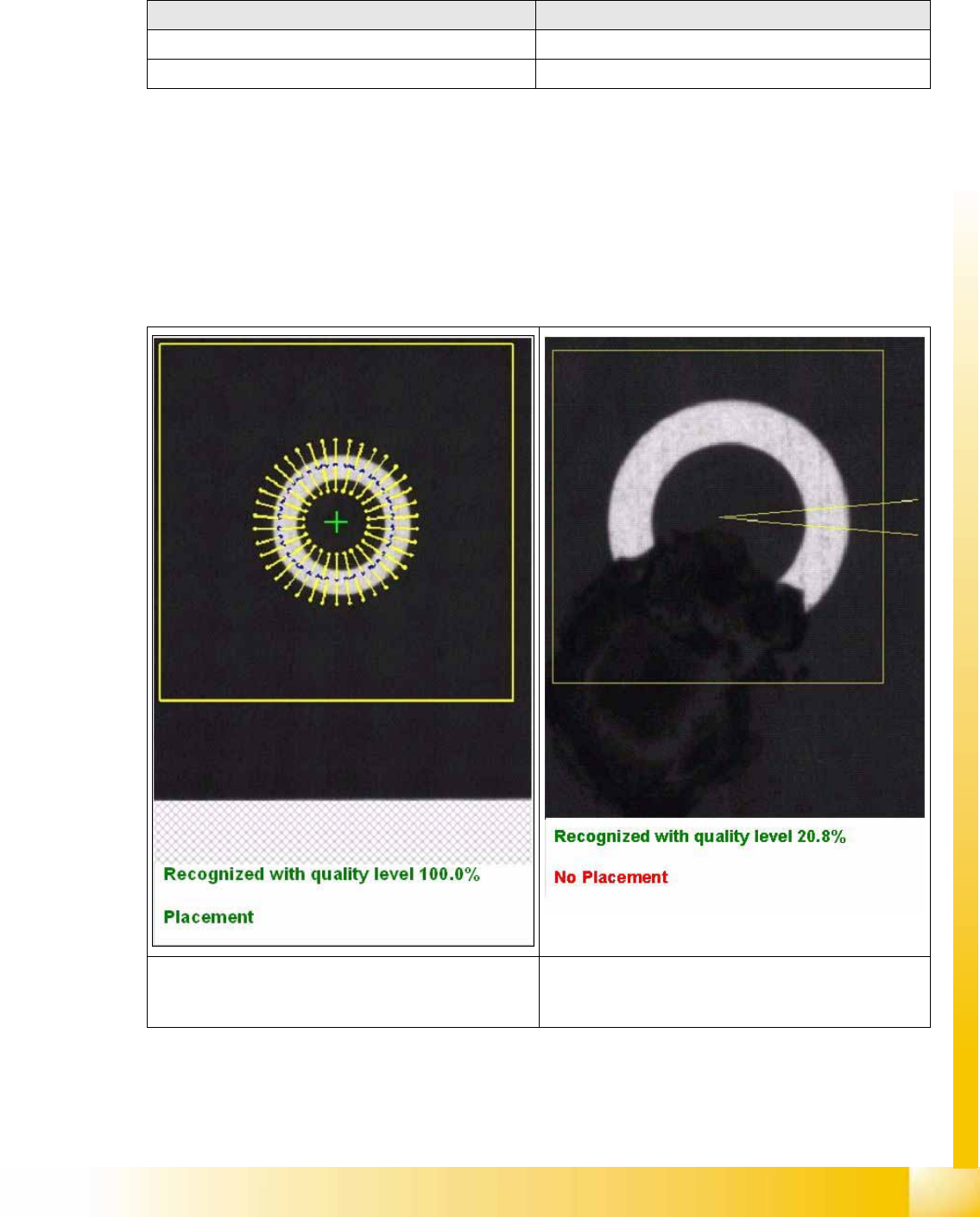
10.1.3 Inkspot Recognition
There are various programming options for inkspot recognition.
The following measurement results are issued for the structure found:
10.1.3.1 Synthetic Inkspots
Nine different synthetic shapes can be programmed. Similar to teaching, the shape, dimensions and the
optical impression – light or dark – of the positive inkspot need to be taught. If the shape is recognized,
the inkspot will be accepted as a positive inkspot for placement. If the shape is not found in the search
field, the inkspot is understood to be a negative inkspot (no time loss for missing structure) and will not
be placed or, in the case of global inkspots, the local panel inkspots will be approached in the case of
no recognition.
When teaching the fiducial: When centering the fiducial:
=> X/Y position values for approach during teaching => No results shown
=> Placement information:place/omit => Placement information: place/omit
The top diagram shows the fine search procedure for
teaching synthetic inkspots, with the corresponding
results.
This diagram above shows the results for an inkspot
which has been marked as bad.
SIPLACE Vision
Optical Fiducial Models Inkspot Recognition
Student Guide Advanced Level 1 SIPLACE D-Series
SIPLACE Vision EN 05/2007
10-8
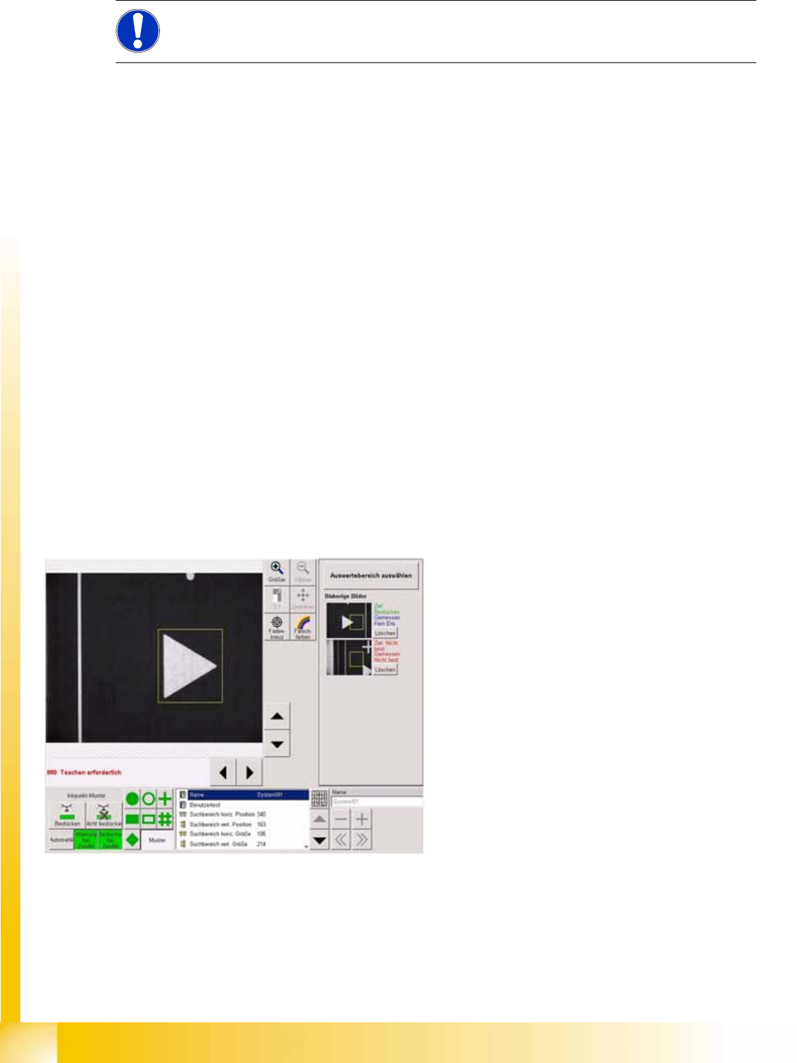
10.1.3.2 Patterns as Inkspots
Other, non-synthetic shapes and structures are taught as good or bad cases.
All images which have been taught are shown in separate fields, with their results.
Teaching is possible in two steps, before placement:
The positive inkspot is taught first, followed by the transportation of a PCB with negative inkspot into the
station, so that the negative inkspot can then be taught.
This taught inkspot has three areas:
Positive inkspot for placement
Negative inkspot for omission
If in doubt (if you are unable to assign the inkspot because, for example, the inkspot has not been
correctly struck through). After completion of the teaching procedure, press the Automatic button.
The teaching function/procedure:
Select the inkspot to be taught from the fiducials list.
Place the board (with the various inkspots) into the input conveyor; press the Center fiducial button
to transport the board into the processing conveyor, where it will be clamped into place and the
gantry is positioned over the first inkspot.
Teach the inkspot accordingly, as either positive or negative in the Geometry menu.
Press Move to next fiducial until the second version of the inkspot appears under the camera.
Teach this inkspot with the same fiducial field.
After completion of the teaching procedure, press the Automatic button.
NOTE:
For bad mark teaching (ink spot) the fiducial area center is linked to the camera center.
10-2: SC pattern as inkspots 01 0505
The programmed inkspot coordinates position the
camera above the fiducial, so that the evaluation
area can be programmed.