D-serie level 1 EN.pdf - 第186页
SIPLACE Measuring Tools Track Signal Tester [00322510-01] S tuden t Guide Advanced Level 1 SIPLACE D-Series SIPLACE Measuring T o ols EN 05/2007 11 - 2 1 1.2 T rack Signal T ester [00322510-01] 1 1.3 T rack Signal T este…
SIPLACE Measuring Tools
Axis Test Box (Old Version) and Adapter Board
Student Guide Advanced Level 1 SIPLACE D-Series
EN 05/2007 SIPLACE Measuring Tools
11-1
11 SIPLACE Measuring Tools
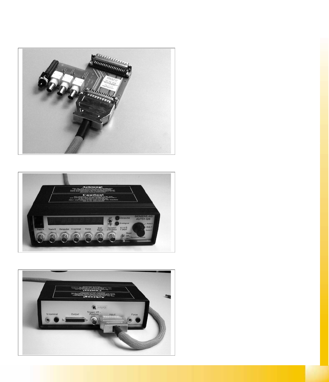
11.1 Axis Test Box (Old Version) and Adapter Board
Item No.: Axis test box, including adapter board [00303430-06]
Item No.: Axis test box [00328041-05]
Item No.: Cable [00304771-03]
Item No.: Adapter board [00328040-01]
Application:
Compare the axis dynamics of the placement head and gantry axes.
Adapter board for axis text box
Item No.: [00328040-01]
Axis test box SIPLACE – front
Item No.: [00328041-05]
Axis test box SIPLACE – back
Item No.: [00328041-05]
SIPLACE Measuring Tools
Track Signal Tester [00322510-01]
Student Guide Advanced Level 1 SIPLACE D-Series
SIPLACE Measuring Tools EN 05/2007
11-2
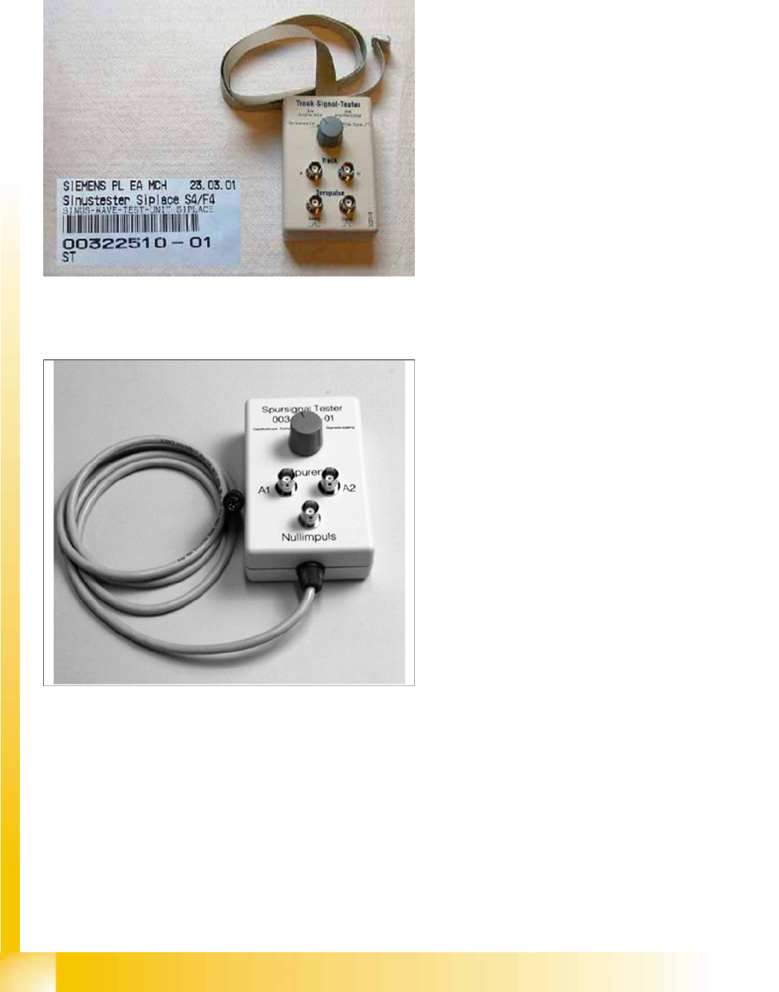
11.2 Track Signal Tester [00322510-01]
11.3 Track Signal Tester [00343785-01]
Track signal tester
Application:
The track signal tester is used to check the
track signals of the incremental measuring
systems - particularly for the head axes. It is
also used for the gantry axes in older
SIPLACE machines (S20, F4).
Track signal tester
Application:
The track signal tester is used to check the
track signals of the incremental measuring
systems for the gantry axes (from SIPLACE
HS50).
SIPLACE Measuring Tools
SIPLACE Axis Tester (SAT) [03002801-01]
Student Guide Advanced Level 1 SIPLACE D-Series
EN 05/2007 SIPLACE Measuring Tools
11-3
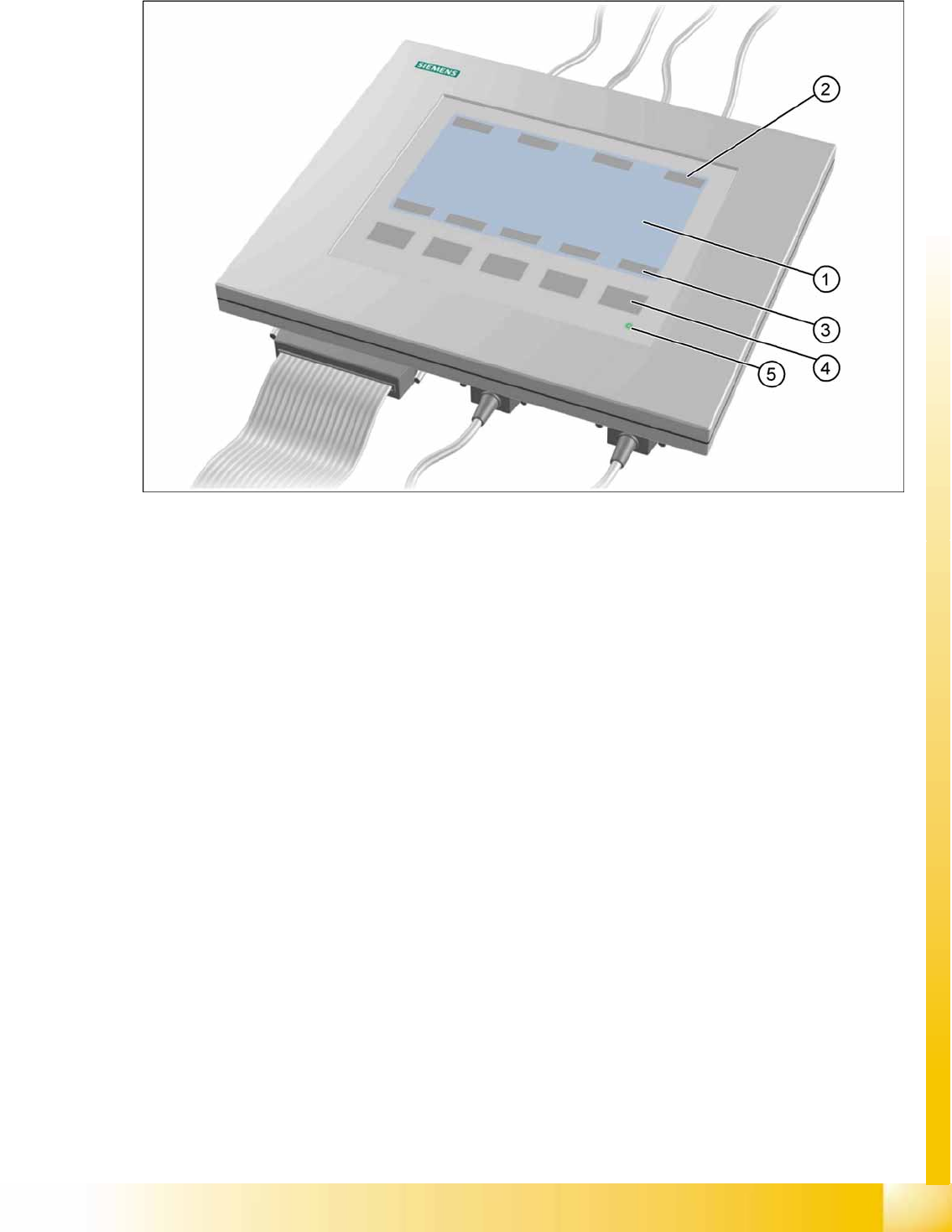
11.4 SIPLACE Axis Tester (SAT) [03002801-01]
11-1: Axis tester - view from above
Legend
1. LCD display with 240 x 128 pixels, black-and-white display, with background lighting
The LCD display shows the menus and a graphic of the recorded trigger, track and position signals.
The relevant parameters, such as
– Time basis,
– Time measurement values,
– Signal level and
– Cursor positions with the corresponding time difference values
are blended in as alphanumerical details in the measurement curve graphics.
2. Dynamic function display of BNC socket assignment on the LCD display
3. Dynamic function display of membrane key assignment on the LCD display
4. Five membrane keys for using the menu
5. Green LED for displaying the operational mode