D-serie level 1 EN.pdf - 第188页
SIPLACE Measuring Tools SIPLACE Axis Tester (SAT) [03002801-01] S tuden t Guide Advanced Level 1 SIPLACE D-Series SIPLACE Measuring T o ols EN 05/2007 11 - 4 11-2: Axis tester - view from below
SIPLACE Measuring Tools
SIPLACE Axis Tester (SAT) [03002801-01]
Student Guide Advanced Level 1 SIPLACE D-Series
EN 05/2007 SIPLACE Measuring Tools
11-3
11.4 SIPLACE Axis Tester (SAT) [03002801-01]
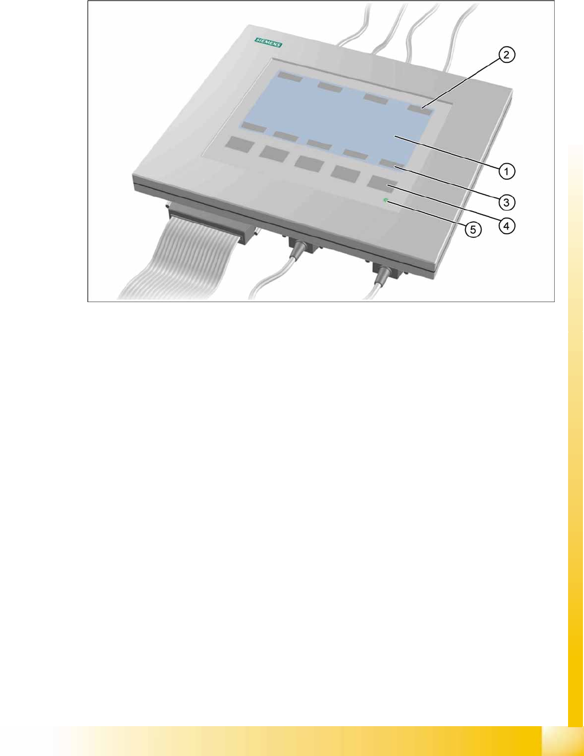
11-1: Axis tester - view from above
Legend
1. LCD display with 240 x 128 pixels, black-and-white display, with background lighting
The LCD display shows the menus and a graphic of the recorded trigger, track and position signals.
The relevant parameters, such as
– Time basis,
– Time measurement values,
– Signal level and
– Cursor positions with the corresponding time difference values
are blended in as alphanumerical details in the measurement curve graphics.
2. Dynamic function display of BNC socket assignment on the LCD display
3. Dynamic function display of membrane key assignment on the LCD display
4. Five membrane keys for using the menu
5. Green LED for displaying the operational mode
SIPLACE Measuring Tools
SIPLACE Axis Tester (SAT) [03002801-01]
Student Guide Advanced Level 1 SIPLACE D-Series
SIPLACE Measuring Tools EN 05/2007
11-4
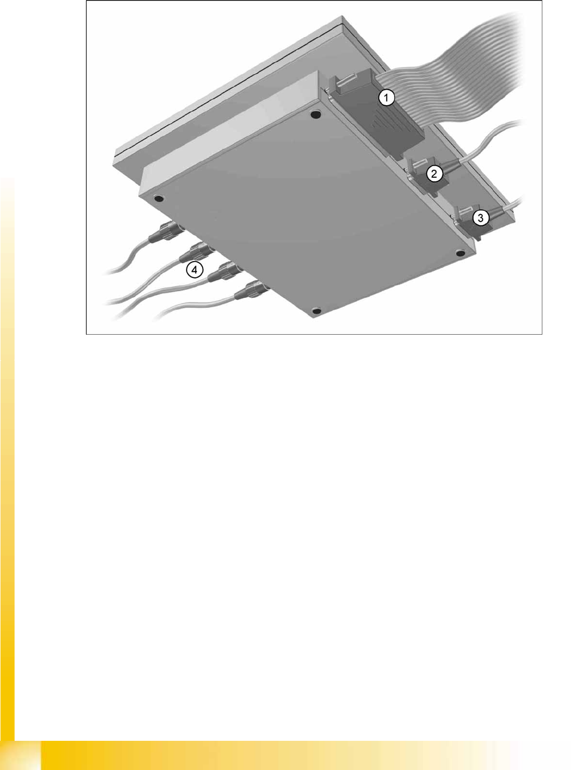
11-2: Axis tester - view from below

SIPLACE Measuring Tools
Scope of Delivery SIPLACE Axis Tester (SAT) [03002801-01]
Student Guide Advanced Level 1 SIPLACE D-Series
EN 05/2007 SIPLACE Measuring Tools
11-5
Legend
1. Connection for flat ribbon cable:
– On the axis tester side:
– 37-pin Sub-D connector
– On the axis control side:
– 37 pin Sub-D connector for the S-20/23/25/F4/F5 and HS-50 machines, with the axis control
units A361 or A362
– 25 pin Sub-D connector for the S-15/F3, G machines and the wafflepack changer, with the axis
control unit A360
An adapter is attached to the flat ribbon cable so that the 25 pin axis control unit can be
connected.
Operating voltages of
+5 V- ±5 % and
±15 V- ±5 %
are supplied via the 37 pin flat ribbon cable from the axis control unit of the axis tester.
2. 9 pin Sub-D connector for the CAN Bus cable e.g. to connect CAN Bus-controlled boards in the
machines - currently not in used (transmission rate 128 kBaud to 1 MBaud, impedance 120 Ohm)
3. 9 pin Sub-D connector for the serial interface cable (V24) used during software download, e.g. for
connection of an external PC (max. transmission rate up to 188 kBaud)
4. Four BNC sockets, impedance 50 Ohm. The socket assignment can be programmed as required.
They can be assigned the following signals:
– Track signal A or B TTL level, max. 5 V
– Zero pulse TTL-level tmin = 1 µsec
– End position signal TTL level tmin > 10 msec
– Trigger TTL level tmin > 10 msec
– Count error TTL level, trigger signal from count error sensor for the oscilloscope
– Vnom ±10 V, analog signal, Ri = 10 kOhm
– Force ±10 V analog signal, Ri = 10 kOhm
– VREG (total current) ±10 V analog signal, Ri = 10 kOhm
– Positions deviation ±10 V analog signal; signal is generated in the axis tester.
11.4.1 Scope of Delivery
The SIPLACE AxisTester, complete package [03002801-01] includes the following components:
SIPLACE AxisTester [03000761-01]
Test cable A361 ... A363 (length 150 cm) with 37 pin connector and 37 pin socket, for connection to
the axis control units of S2x, F4/F5 and HS machines [03002803-01]
CAN Bus cable [00349679-03]
RS232-C cable [03002804-01]
Axis tester manual [00193370-01]