D-serie level 1 EN.pdf - 第24页
Operational Safety Room for Your Sketches and Notes Dispatching ESD Assemblies S tuden t Guide Advanced Level 1 SIPLACE D-Series Operational Safety EN 05/2007 2-10

Operational Safety
Dispatching ESD Assemblies Room for Your Sketches and Notes
Student Guide Advanced Level 1 SIPLACE D-Series
EN 05/2007 Operational Safety
2-9
2.6 Room for Your Sketches and Notes

Operational Safety
Room for Your Sketches and Notes Dispatching ESD Assemblies
Student Guide Advanced Level 1 SIPLACE D-Series
Operational Safety EN 05/2007
2-10
Overview
General
Student Guide Advanced Level 1 SIPLACE D-Series
EN 05/2007 Overview
3-1
3 Overview
Unless otherwise specified, the overview is based on the example of a D4 machine.
3.1 General
The high-speed SIPLACE D4 placement machine combines high placement performance with accuracy
and flexibility. The machines use the Collect&Place placement method.
The SIPLACE D4 placement machine is equipped with four gantries, for fast and accurate positioning
along the X and Y axes.
Each gantry has a 12-segment C&P head (C&P12). Each placement area is served by two gantries:
Placement area 1 Gantries 1 and 4
Placement area 2 Gantries 2 and 3
The components are optically centered with the help of a digital Vision module. Two different component
cameras are available for the placement heads: a standard camera and a high-resolution component
camera.
A five-segment PCB conveyor, consisting of input conveyor, processing conveyor 1, intermediate
conveyor, processing conveyor 2 and output conveyor, transports the components to the processing
positions. PCB transport can be performed with a single or flexible dual conveyor (with stationary side
either on the left or right). A PCB camera is used to optically center the boards.
See also:
J 1.2 SIPLACE on the World Wide Web (WWW) [J1-3]
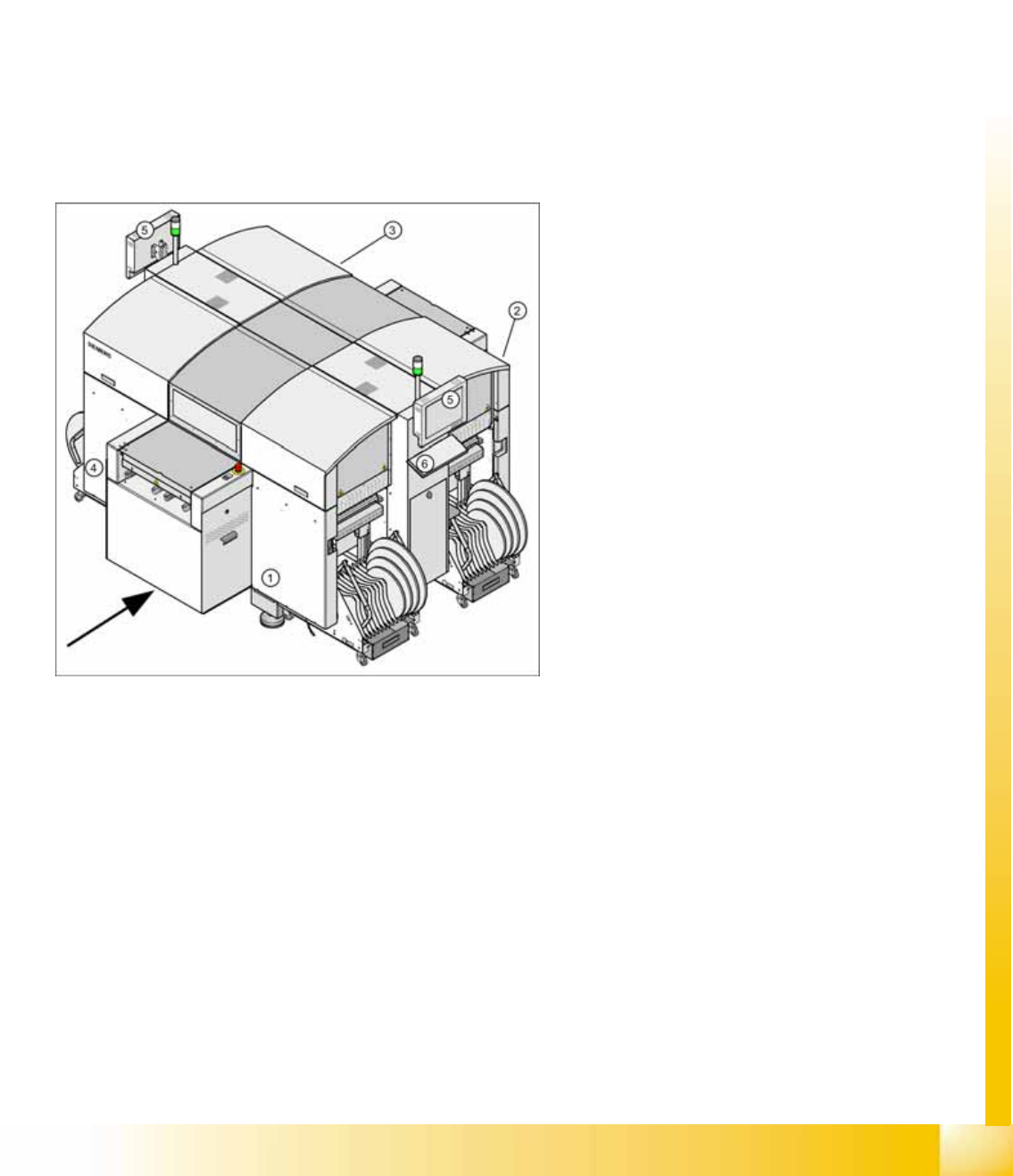
3-1: SIPLACE D4 placement machine
Legend
1. Sector 1
2. Sector 2
3. Sector 3
4. Sector 4
5. Monitor (on both sides)
6. Keyboard (on both sides)