D-serie level 1 EN.pdf - 第36页
Overview Assemblies Axis Unit and Computer Unit S tuden t Guide Advanced Level 1 SIPLACE D-Series Overview EN 05/2007 3-12 3.4.3.2 Control Unit Comp arison D1 to D4 The control units can be accessed from the left machine…
Overview
Axis Unit and Computer Unit Assemblies
Student Guide Advanced Level 1 SIPLACE D-Series
EN 05/2007 Overview
3-11
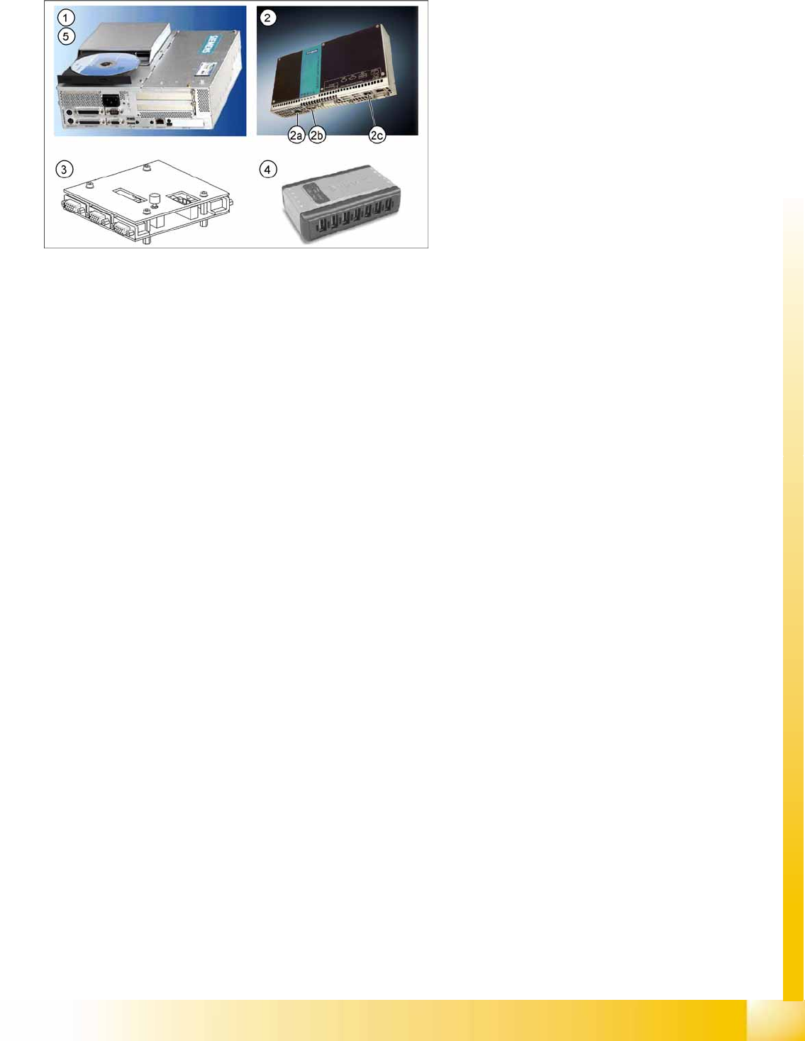
3.4.3.1 Computer Unit
1. Station computer Siemens Simatic Box PC (SR-SW, SIPLACE Vision SW)
2x Hotlink boards for SIPLACE Vision, connected to the digital cameras
4x USB port
2x LAN Ethernet (LAN 1 connected to MC, LAN 2 hub or SIPLACE Pro)
1x VGA connection, connected to Multiplexer (monitor)
Voltage supply 24 V DC
The status display and the H1/H2 are active on the computer counterpart, while the BIOS is loaded.
2. Machine controller Siemens Simatic Micro Box PC (RMOS SW)
2x LAN Ethernet (LAN 1 (2c) connected to SC, LAN 2 - not in use)
4x USB port
1x VGA connection, connected to Multiplexer (monitor)
COM assembly – CAN 1 (2a) for PA1– CAN 2 (2b) for PA2
Voltage supply 24 V DC
3. Multiplexer (switch over between SR and MC)
4. USB hub 2.0 – 4 port (or 7 port)
Voltage supply connection
USB input from station computer
4x (7x) USB outputs - 2x keyboard, 2x touchscreen (3x free)
5. External CD-ROM drive with USB interface (also for MC)
3-6: Computer unit D4
Legend
1. Station computer Siemens Simatic Box PC
2. Machine controller Siemens Simatic Micro Box
PC
3. Multiplexer
4. USB hub
5. USB CD-ROM drive
Overview
Assemblies Axis Unit and Computer Unit
Student Guide Advanced Level 1 SIPLACE D-Series
Overview EN 05/2007
3-12
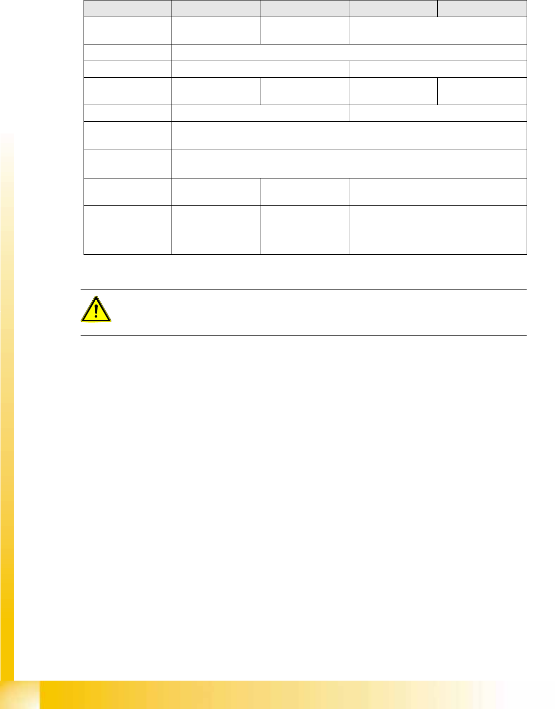
3.4.3.2 Control Unit Comparison D1 to D4
The control units can be accessed from the left machine side, under the PCB input conveyor belt:
Designation D4 D3 D2 D1
Station computer Box PC 627 PC C086 unit
(from 2007 box PC)
Box PC 627
Operating system Windows XP
SC/MC 602.01 / 603.01 603.01
Machine controller SIMATIC
MicroboxPC 420
PC C086 unit
(from 2007 box PC)
SIMATIC
MicroboxPC 420
SIMATIC
MicroboxPC 420
Operating system 602: RMOS / 603: Windows XP Windows XP
Shutdown -
operator
Regular shutdown of SC / SITEST desk
Shutdown
administrator
Shutdown pushup - start button menu
Programs
/
SIPLACE
/
Shutdown ALL
External DVD drive Yes for MC with
Windows installation
Yes for MC with Windows installation
USB connections 4 in SC / 7-fold USB
hub for touchscreen
and keyboard
4 in box PC / 4-fold
USB hub for
touchscreen and
keyboard
4 in SC / 7(4)-fold USB hub for touchscreen
and keyboard
ATTENTION:
Do not switch off!
NEVER switch off during the startup (boot) phase. WINDOWS XP might be unable to restart at
the MC. In this case, you would need to reinstall WINDOWS XP!
Overview
Axis Unit and Computer Unit Assemblies
Student Guide Advanced Level 1 SIPLACE D-Series
EN 05/2007 Overview
3-13
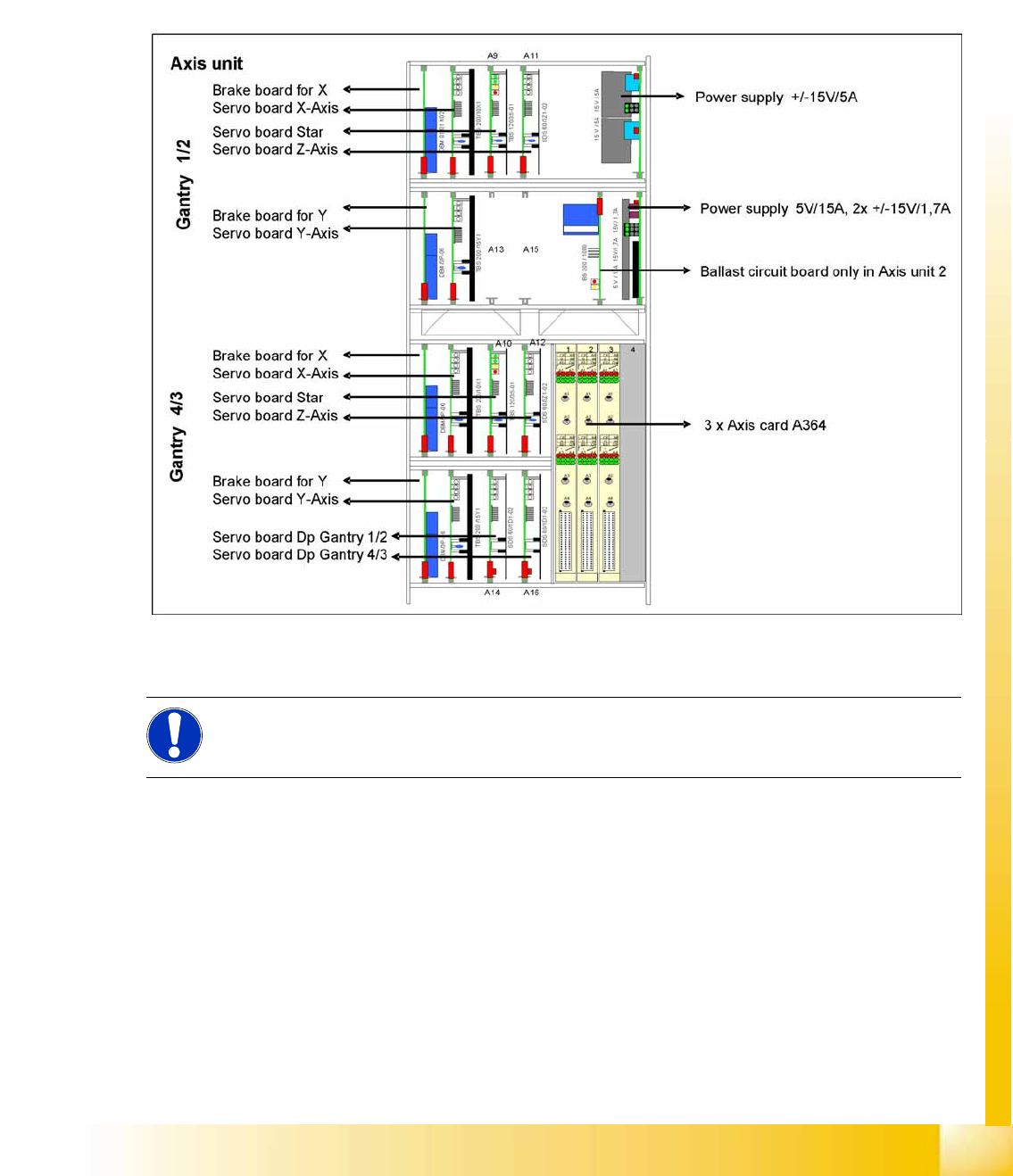
3.4.3.3 Axis Unit
The axis unit contains the servo boards, axis controller boards, power supply (+/-15V,+5V) and the
ballast circuit (only in axis unit 2). The flexible axis unit is equipped with the correct servo and axis boards
for the machine type and head configuration concerned (with C&P12).
Overview of axis unit
D4 machine axis unit in PA1 for gantries 1 and 4 axis unit in PA2 for gantries 2 and 3
Axis Unit SIPLACE D4
3-7: Axis Unit
The axis unit is located near the PCB input or output.
NOTE:
The two power pack assemblies have a different version from 01/2007 and replace the
assemblies shown.