D-serie level 1 EN.pdf - 第39页
Overview Axis Unit and Computer Unit Assemblies S tude nt Guide Advanced Level 1 SIPLACE D-Series EN 05/2007 Overview 3-15 Axis Board A364 3-9: D4 axis board
Overview
Assemblies Axis Unit and Computer Unit
Student Guide Advanced Level 1 SIPLACE D-Series
Overview EN 05/2007
3-14
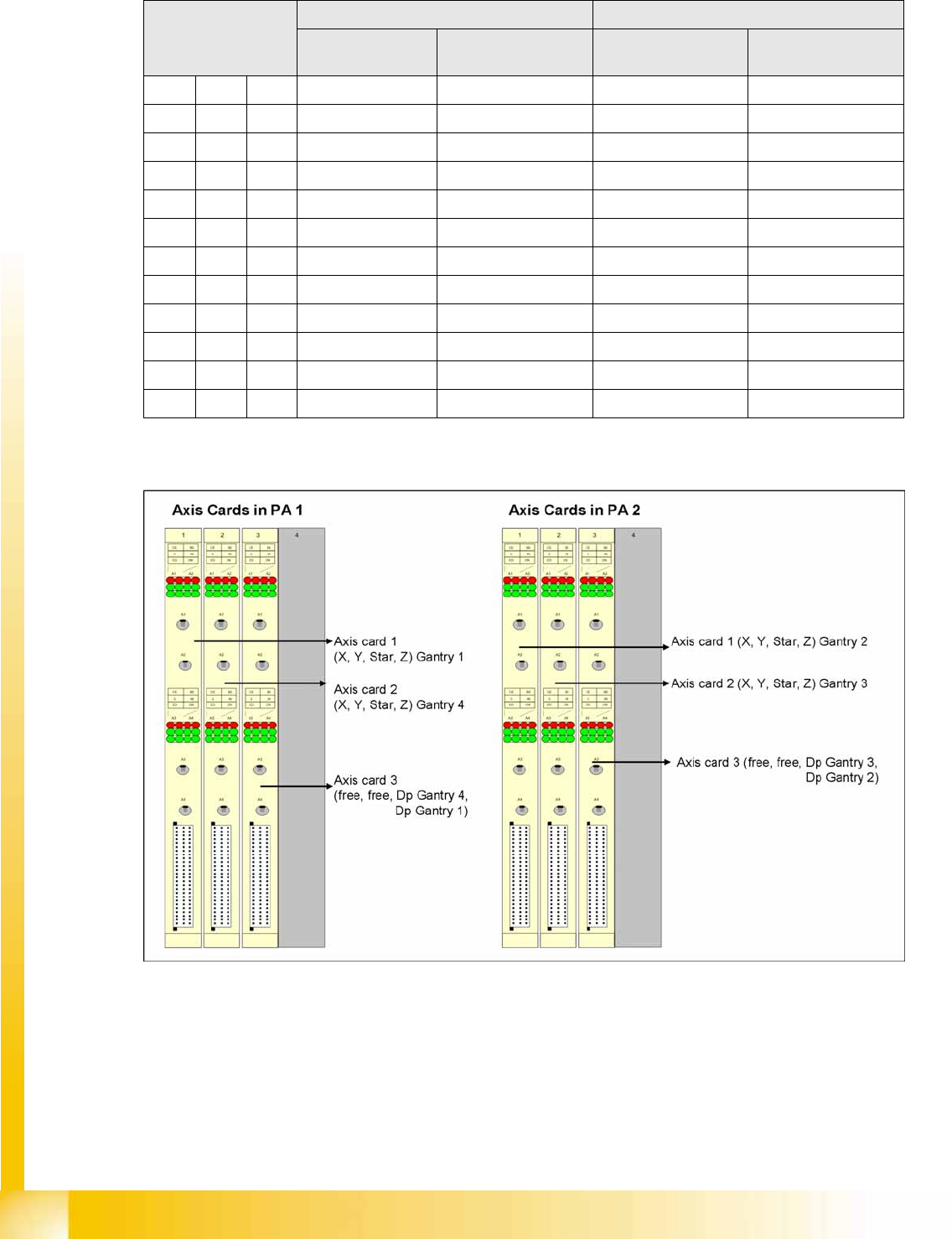
Servo Positions D4/D2
Axis Controller Boards
3-8: Axis controller boards
Servo positions for
each level
D4 D2
C&P type
PA1
C&P type
PA2
C&P type P&P type (next
generation)
x Gantry 1 Gantry 2 Gantry 1 Gantry 1
A9 Star 1 Star 2 Star 1 Z-axis 1
A11 Z-axis 1 Z-axis 2 Z-axis 1 --
Y Gantry 1 Gantry 2 Gantry 1 Gantry 1
A13 -- -- -- D axis 1
A15 -- -- -- --
x Gantry 4 Gantry 3 Gantry 2 Gantry 2
A10 Star 4 Star 3 Star 2 Z-axis 2
A12 Z-axis 4 Z-axis 3 Z-axis 2 --
Y Gantry 4 Gantry 3 Gantry 2 Gantry 2
A14 DP axis G1 DP axis G2 DP axis G1 D axis 2
A16 DP axis G4 DP axis G3 DP axis G2 --
Servo Assignment D4/D2
Overview
Axis Unit and Computer Unit Assemblies
Student Guide Advanced Level 1 SIPLACE D-Series
EN 05/2007 Overview
3-15
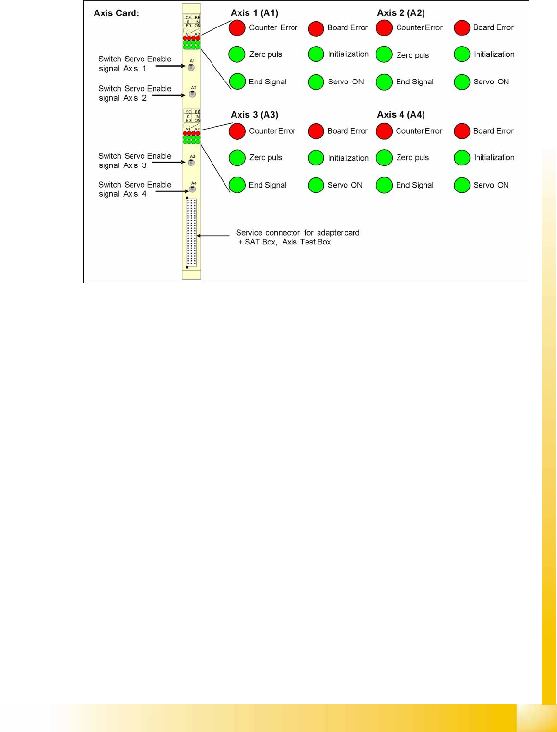
Axis Board A364
3-9: D4 axis board
Overview
Assemblies Pneumatic Unit
Student Guide Advanced Level 1 SIPLACE D-Series
Overview EN 05/2007
3-16
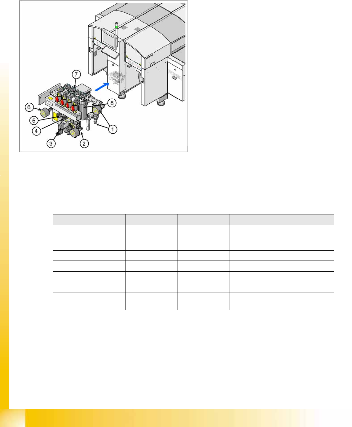
3.4.4 Pneumatic Unit
The pneumatic unit is a fixed installation inside the machine and is located to the right of the middle
section of the machine, behind a flap. The pneumatic unit includes all electrical connections for control/
regulation of the compressed air supply.
3.4.4.1 Compressed Air Distributor Block
The pneumatic unit is used to prepare and distribute the compressed air required in the machine.. The
pressure at the compressed air connection must be at least 5.5 bar.
The following pneumatic circuits are supplied with compressed air via the distributor block:
3-10: D3/D4 pneumatic unit as rack unit
Legend
1. Compressed air connection with main shutoff
valve and manometer
2. 4x connection for bulkcase feeder with
manometer, adjustable (2.5 bar), location 1-4
3. 4x connection for cutters, location 1 - 4 (5 bar)
2x connection for conveyor lifting table
4. 4x connection for nozzle changer (5 bar)
5. 4x connection for docking/undocking
changeover table (5 bar)
6. Electronic control valve with manometer for
regulated machine pressure 5.x bar.
7. 4x connection for gantries 1 - 4, vacuum
generation C&P head with shutoff valves
8. Compressed air filter
D4 D3 D2 D1
Gantries Vacuum
generation Placement
heads
5.1 +/-0.1 bar 5.1 +/-0.1 bar 5.1 +/-0.1 bar 5.1 +/-0.1 bar
Conveyor System 5.1 +/-0.1 bar 5.1 +/-0.1 bar 5.1 +/-0.1 bar 5.1 +/-0.1 bar
tape cutter 5.1 +/-0.1 bar 5.1 +/-0.1 bar 5.1 +/-0.1 bar 5.1 +/-0.1 bar
Nozzle Changer 5.1 +/-0.1 bar 5.1 +/-0.1 bar 2.5 +/-0.1 bar 2.5 +/-0.1 bar
Feed-in units 5.1 +/-0.1 bar 5.1 +/-0.1 bar 5.1 +/-0.1 bar 5.1 +/-0.1 bar
Bulkcase feeder Manually set 2.5
bar
Manually set 2.5
bar
Manually set 2.5
bar
Manually set 2.5
bar
Overview of compressed air supply