D-serie level 1 EN.pdf - 第46页
Overview Assemblies Gantry S tuden t Guide Advanced Level 1 SIPLACE D-Series Overview EN 05/2007 3-22 3.4.7.2 X-Axis Construction 3-17: X-axis design Legend The following modules are installed on t he head mount: PCB c…
Overview
Gantry Assemblies
Student Guide Advanced Level 1 SIPLACE D-Series
EN 05/2007 Overview
3-21
3.4.7 Gantry
3.4.7.1 General
Precise distance measuring systems determine the position of the X and Y axes. This involves the
optoelectronic detection of marker lines on the incremental scales and the transmission of the track
signals to the axis control point in the control unit.
Direct drive techniques are then used to position the placement heads in the Y direction (in the X
direction also for D3 machines). This prevents the typical frictional loss which occurs when complex drive
systems are used. This solution also avoids the wear and tear which can significantly impair the accuracy
of positioning systems over time.
X-axis drive
With the help of a toothed belt, the rotary movement of the X-axis motor is directly converted into a
lengthwise movement of the placement head, in the X-direction.
Y-axis drive
A linear motor moves the placement head lengthwise, in the Y direction.
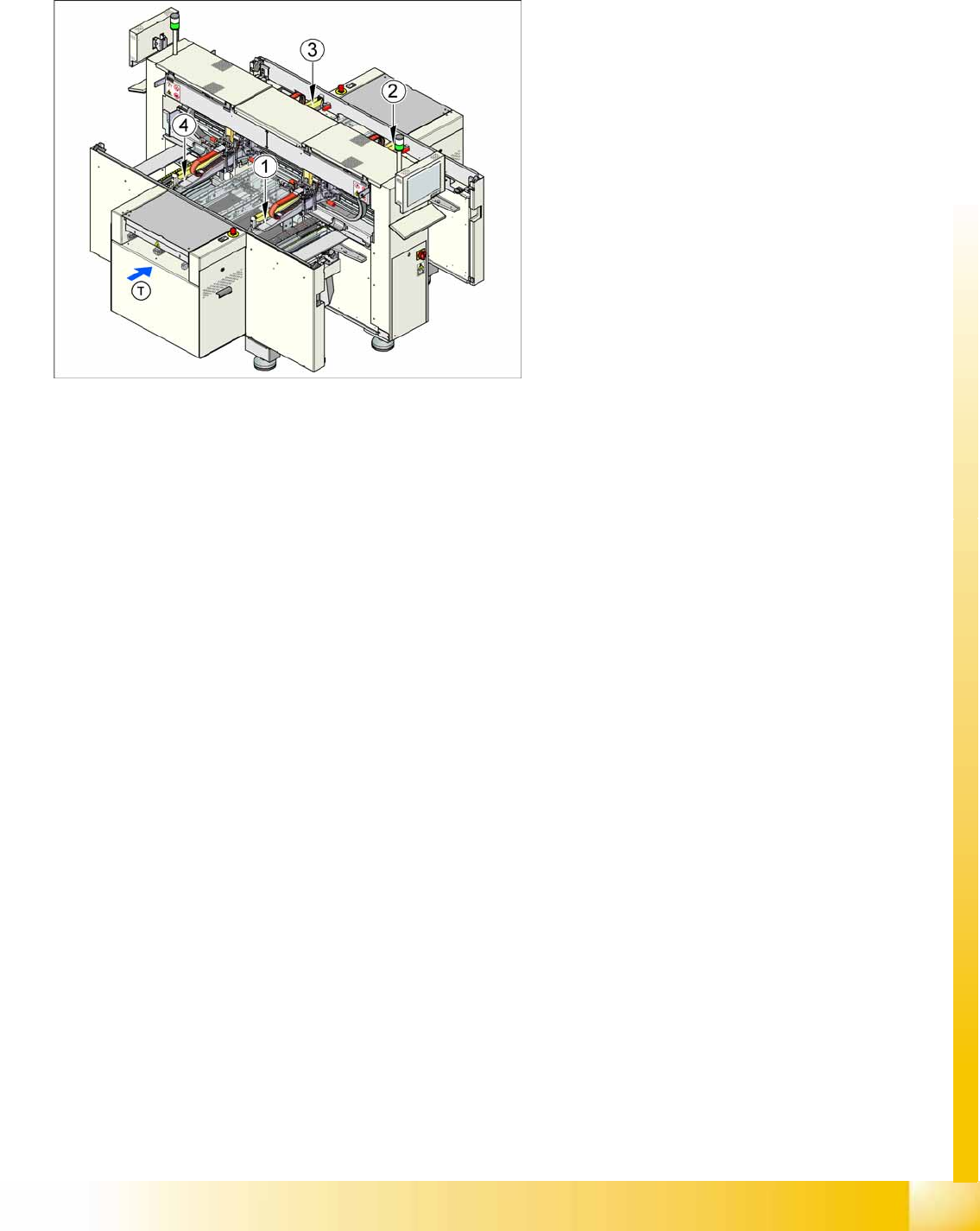
3-16: Machine gantries
Legend
1. Gantry 1
2. Gantry 2
3. Gantry 3
4. Gantry 4
The D4 placement machine is equipped with four
gantries. These are used to accurately and
independently position the four C&P heads in the
X and Y directions.
Due to their construction, the gantries are resistant
to buckling. The precise mechanical guidance of
the axes is achieved with the aid of ball bearing
units.
Overview
Assemblies Gantry
Student Guide Advanced Level 1 SIPLACE D-Series
Overview EN 05/2007
3-22
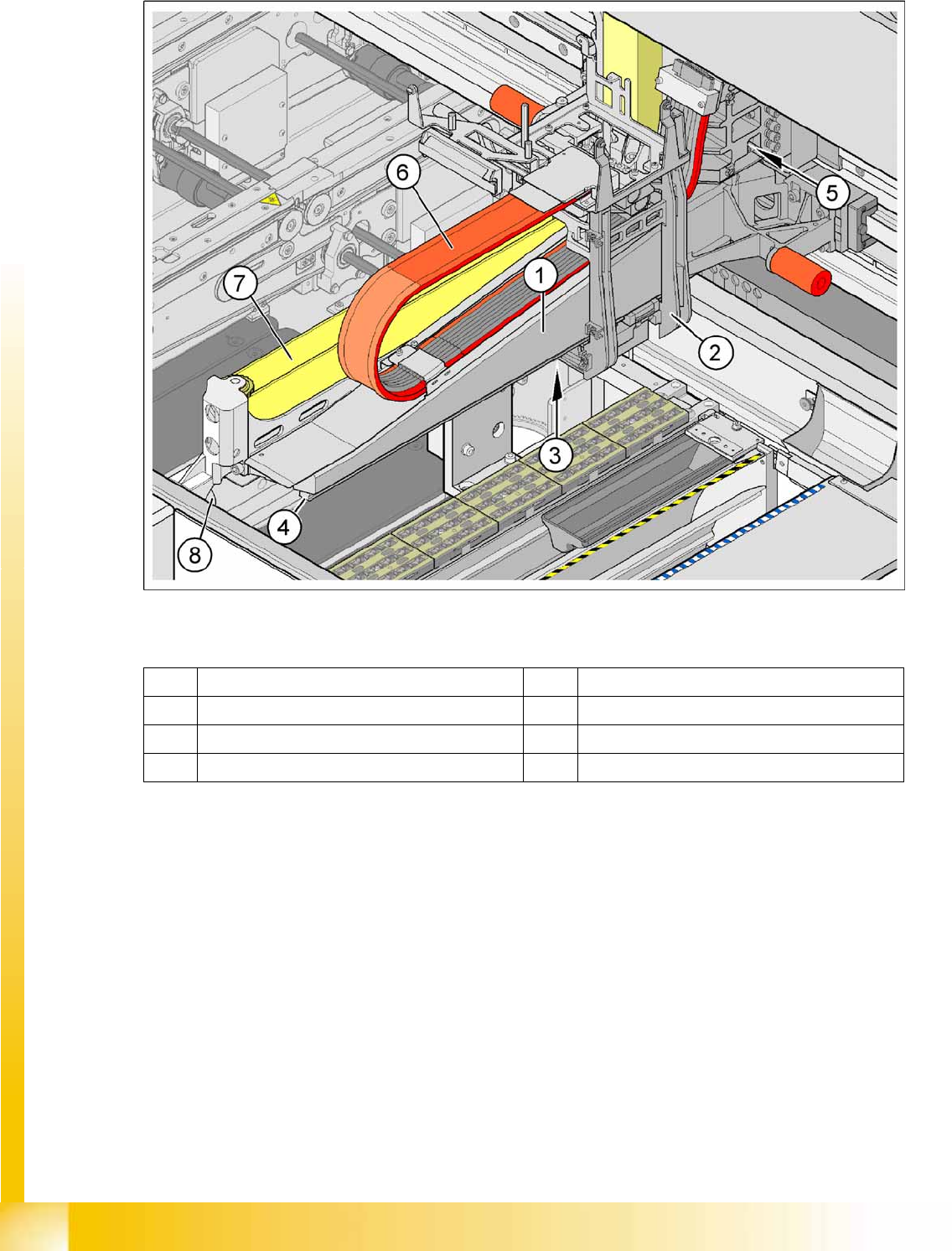
3.4.7.2 X-Axis Construction
3-17: X-axis design
Legend
The following modules are installed on the head mount:
PCB camera
Gantry head distributor
Vision board
16 bit processor board (TQ module)
Incremental encoder
C&P12 head (D4)
or with head modularity C&P12 or C&P6 head (D3/D2/D1)
1 Gantry arm 5 A.C. servo motor with toothed belt
2 Head mount 6 Trailing cable
3 Linear measuring system 7 X belt
4 X guide system 8 Bumper
Overview
Gantry Assemblies
Student Guide Advanced Level 1 SIPLACE D-Series
EN 05/2007 Overview
3-23
X-Axis Technical Data
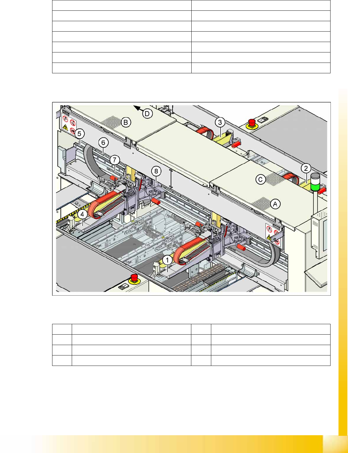
3.4.7.3 Y-Axis Construction
3-18: Y-Axis Design and Fan Positions (D4)
Legend
Drive A.C. servo motor/toothed belt
Maximum speed 2.5 m/sec.
Travel range 375 mm
Distance measuring system Incremental scale
Measuring length 400 mm
Scale length 420 m
Resolution 1 µm
1 Gantry 1 5 Guide system
2 Gantry 2 6 Linear motor secondary part
3 Gantry 3 7 Measuring system
4 Gantry 4 8 Linear motor primary part