D-serie level 1 EN.pdf - 第54页
Overview Assemblies SIPLACE Vision S tuden t Guide Advanced Level 1 SIPLACE D-Series Overview EN 05/2007 3-30 T echnical Dat a 3.4.9.4 Component Camera C&P12 (Op tional, T ype 29) T echnical Dat a Compon ent dimensio…
Overview
SIPLACE Vision Assemblies
Student Guide Advanced Level 1 SIPLACE D-Series
EN 05/2007 Overview
3-29
3.4.9.2 Optional Digital Component Camera C&P12 (Type 38)
Technical Data
3.4.9.3 Digital Component Camera C&P12 (Type 28)
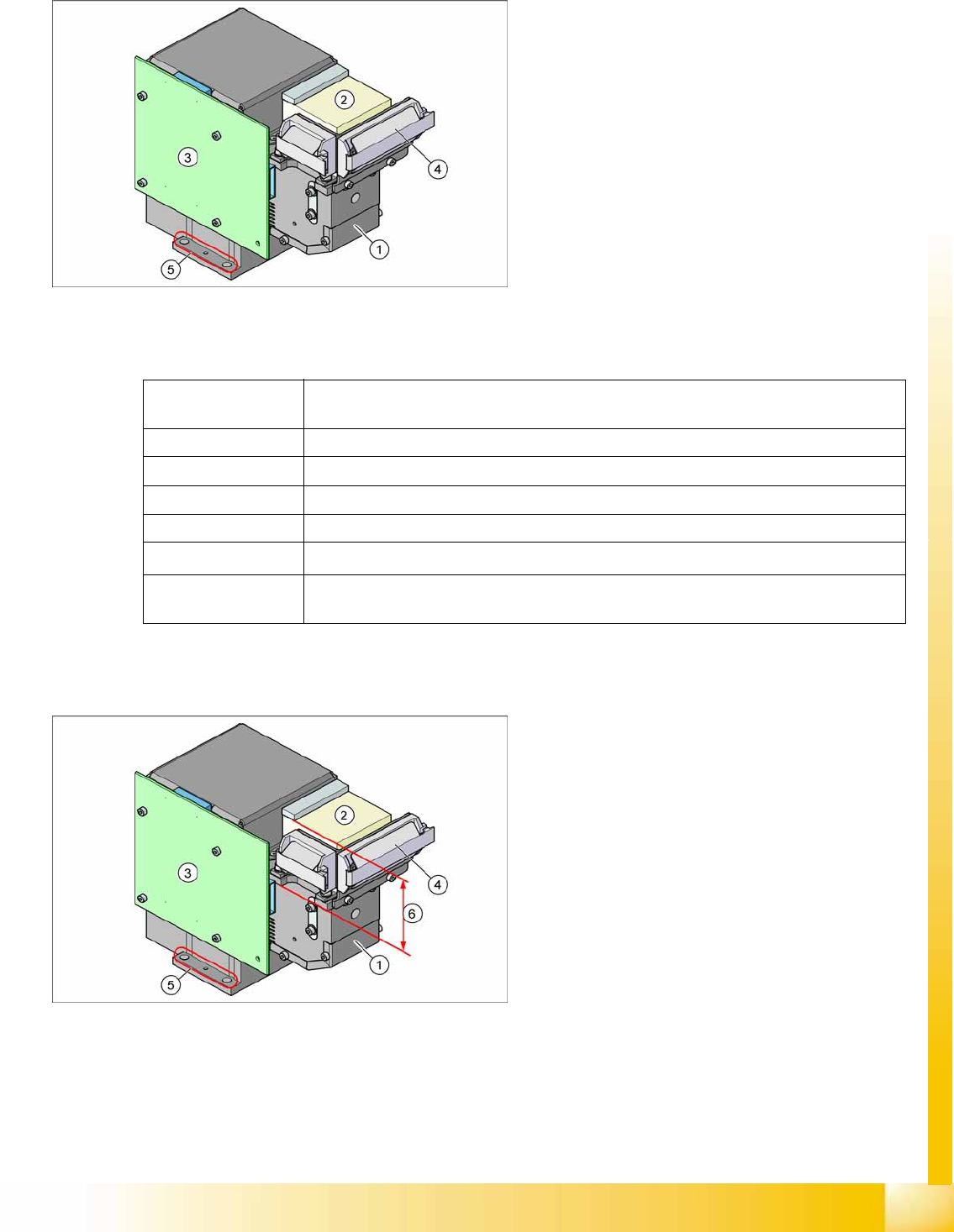
3-22: Component camera as option on the C&P12 head
Legend
1. Component camera optics and illumination
2. Camera amplifier
3. Illumination control
4. Flat ribbon cable holder for C&P head leads
5. Camera fixtures
2 x fixture drillings and 1 x centering drilling
each on both sides
The camera type 38 can be recognized by its type
label.
Component
dimensions
0.2 x 0.1 mm
2
to 16 x 16 mm
2
Component range 0.2 x 0.1 mm² (01005) to PLCC36 (32R)
Min. lead pitch 0,1 mm
Min. ball pitch 0.25 mm
Min. ball diameter 0.14 mm
Field of view
20.5 x 20.5 mm
2
Method of
illumination
Front lighting (6 programmable options on 4 levels )
Technical data for camera type 38
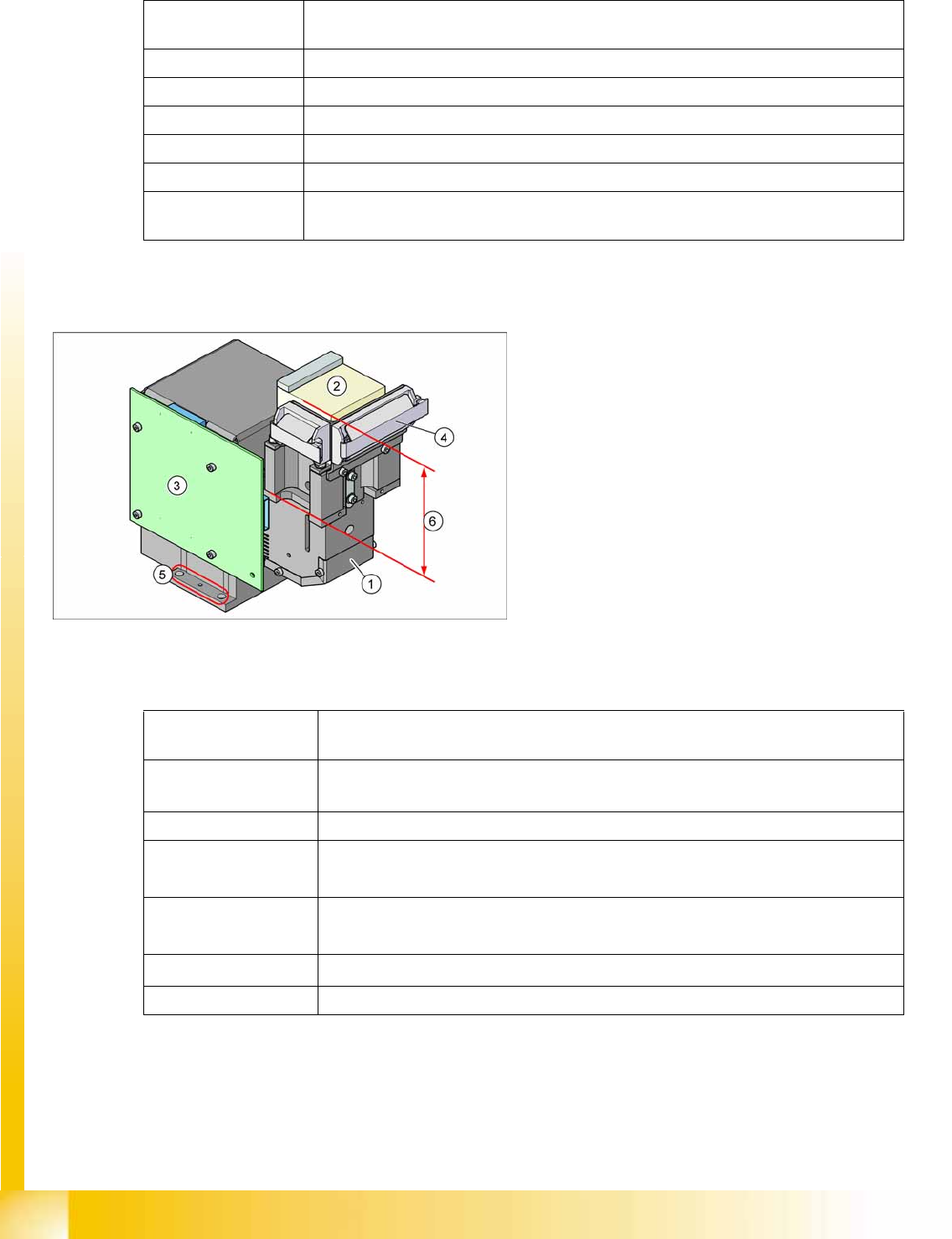
3-23: Component camera as default on the C&P12 head
Legend
1. Component camera optics and illumination
2. Camera amplifier
3. Illumination control
4. Flat ribbon cable holder for C&P head leads
5. Camera fixtures
2 x fixture drillings and 1 x centering drilling
each on both sides
6. The low construction helps you to differentiate
camera type 28 from camera type 29.
Overview
Assemblies SIPLACE Vision
Student Guide Advanced Level 1 SIPLACE D-Series
Overview EN 05/2007
3-30
Technical Data
3.4.9.4 Component Camera C&P12 (Optional, Type 29)
Technical Data
Component
dimensions
0.5 x 0.5 mm
2
to 18.7 x 18.7 mm
2
Component range 0402 to PLCC44 incl. BGA, µBGA, flip-chip, TSOP, QFP, SO to SO32, DRAM
Min. lead pitch 0.5 mm
Min. ball pitch 0.45 mm
Min. ball diameter 0.25 mm
Field of view 24.5 x 24.5 mm2
Method of
illumination
Front lighting (6 programmable options on 4 levels )
Technical data for camera type 28
3-24: Component camera as default on the C&P12 head
Legend
1. Component camera optics and illumination
2. Camera amplifier
3. Illumination control
4. Flat ribbon cable holder for C&P head leads
5. Camera fixtures
2 x fixture drillings and 1 x centering drilling
each on both sides
6. The high construction helps you to
differentiate camera type 29 from camera type
28.
Component
dimensions
0.3 x 0.3 mm
2
to 27 x 27 mm
2
Component range
0201 to 27 x 27 mm
2
PLCC, SO, QFP, TSDP, SOT, MELF, CHIP, IC, BGA
Min. lead pitch 0.3 mm
Min. ball pitch
0.25 mm for component < 18 x 18 mm
2
0.35 mm for component ≥ 18 x 18 mm
2
Min. ball diameter
0.14 mm for component < 18 x 18 mm
2
0.2 mm for component ≥ 18 x 18 mm
2
Field of view
31 x 31 mm
2
Method of illumination Front lighting (6 programmable options on 4 levels )
Technical data for camera type 29
Overview
SIPLACE Vision Assemblies
Student Guide Advanced Level 1 SIPLACE D-Series
EN 05/2007 Overview
3-31
3.4.9.5 Component Camera (Standard Type 36, Option Type 33)
Technical Data
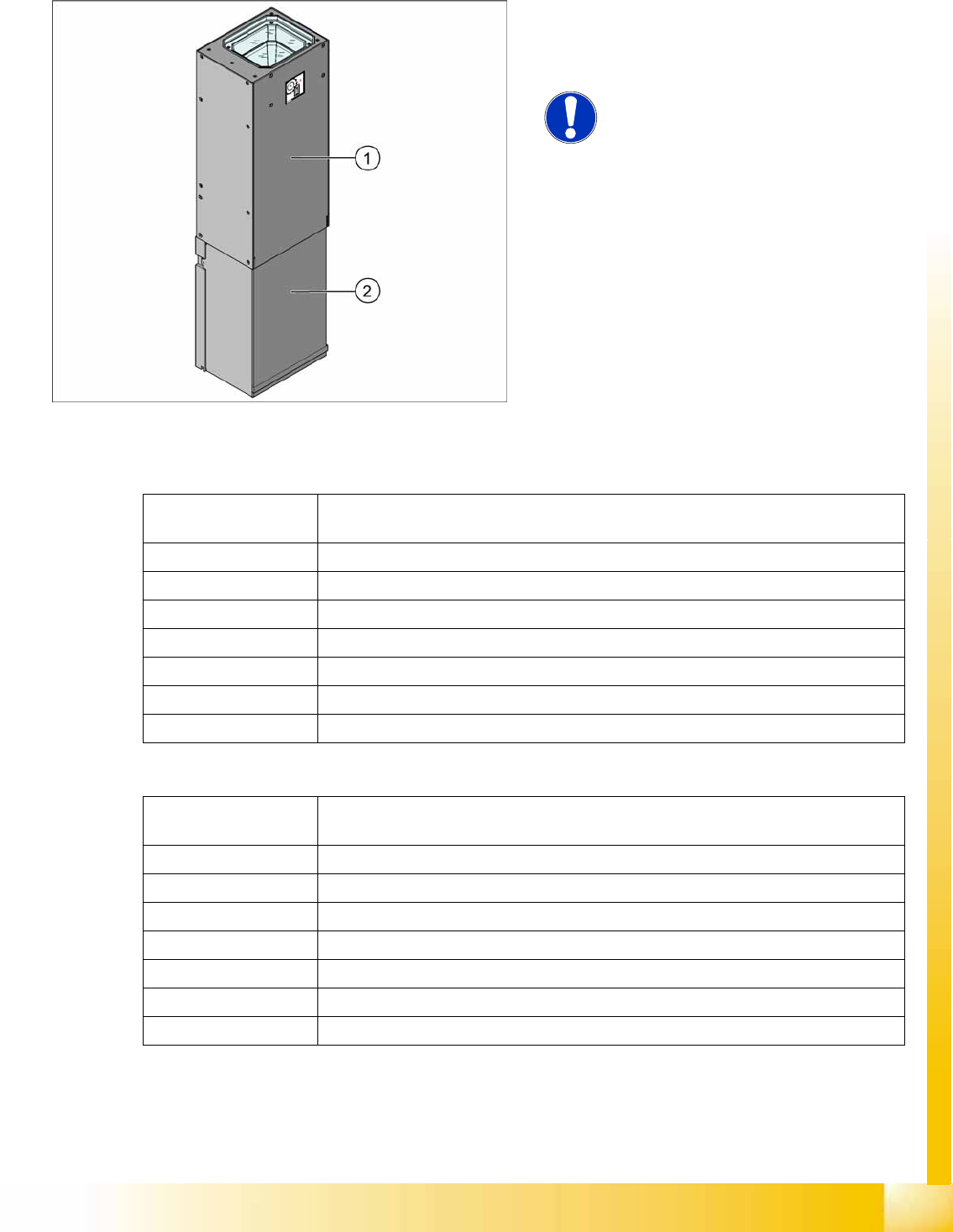
3-25: Component camera for Twin head (D3) or P&P module (D1)
Legend
1. Top section with camera lens system
2. Lower camera cover
NOTE:
The standard camera (type 36) and the
optional camera (type 33) can be
recognized by their labels.
Component
dimensions
0.8 x 0.8 mm² to 32 x 32 mm² (simple measurement)
Component range 0603, MELF, SO, PLCC, QFP, electrolytic capacitors, BGA
Min. lead pitch 0.4 mm
Min. lead width 0.24 mm
Min. ball pitch 0.56 mm
Min. ball diameter 0.32 mm
Field of view 38 x 38 mm²
Method of illumination Front lighting (6 programmable options on 4 levels )
Technical data for camera type 36
Component
dimensions
0.8 x 0.8 mm² to 55 x 45 mm² (simple measurement)
Component range 0603, MELF, SO, PLCC, QFP, electrolytic capacitors, BGA
Min. lead pitch 0.3 mm
Min. lead width 0.15 mm
Min. ball pitch 0.45 mm
Min. ball diameter 0.25 mm
Field of view 65 x 50 mm² simple measurement
Method of illumination Front lighting (6 programmable options on 4 levels )
Technical data for camera type 33