D-serie level 1 EN.pdf - 第70页
Reference Run Reference Run (D-Series) Axis Reference Run S tuden t Guide Advanced Level 1 SIPLACE D-Series Reference Run EN 05/2007 5-2 X Press START button This also switch es the control voltages on. X Preparing the s…

Reference Run
Overview Reference Run (D-Series)
Student Guide Advanced Level 1 SIPLACE D-Series
EN 05/2007 Reference Run
5-1
5 Reference Run
5.1 Reference Run (D-Series)
The placement machine reference run guaranties the correct function for placement in the station SW.
This is where the reference runs for the C&P head and for the gantry are described. A separate chapter
describes the reference run for the P&P module, performed parallel to that for the C&P head.
5.1.1 Overview
The reference run is divided into 4 main steps. Module reference runs for the WPC or for a 2nd
placement head per gantry are not listed at this stage.
1. Conveyor system reference run
This activates the unoccupied (not occupied with a PCB) conveyors.
(in older SW versions, this function can also be performed to conclude the reference run.)
2. Axis reference run
This is divided into:
A.) the head axis reference run and
B.) the gantry axis reference run.
The gantry head axes are started at the same time. As many functions as possible are performed at
the same time.
3. Vacuum reference run
The
A.) vacuum values "open" and "closed" for placement are determined and
B.) all segments in the DP stations are rotated into their 0 degrees positions.
4. Height Reference Run
This function tests the length of the segment nozzles and of the heads in a placement area, on the
top surface of a conveyor side.
These are described and explained in detail below. Machine type or configuration-related extensions or
deviations are explained in separate texts to prevent confusion.
5.1.2 Conveyor Reference Run
The conveyor reference run tests the function of the conveyor belts. This requires the relevant conveyor
belt to be empty i.e. to be free of boards (PCB). If one of the PCB sensors detects a board, this conveyor
belt will not be activated and this board will be transported to the output conveyor of the placement
station, at the end of the complete reference run.
5.1.3 Axis Reference Run
5.1.3.1 Head Axis Reference Run
The C&P6/12 placement heads need to be prepared for the axis reference run.
Sequence:
X Initialize the stepping motor as soon as you have switched on the machine:
Reference Run
Reference Run (D-Series) Axis Reference Run
Student Guide Advanced Level 1 SIPLACE D-Series
Reference Run EN 05/2007
5-2
X Press START button
This also switches the control voltages on.
X Preparing the star axis reference run
The following steps are performed:
– Upwards movement of Z-axis to top end stopper.
– Downwards movement to Z position (30 digits) with reduced force for free star movement.
5-1: Initializing stepping motor at DP-station (1)
Legend
1. Home position DP drive around 1 mm away
from segment
The DP station has swiveled approx. 1 mm
away from the segment.
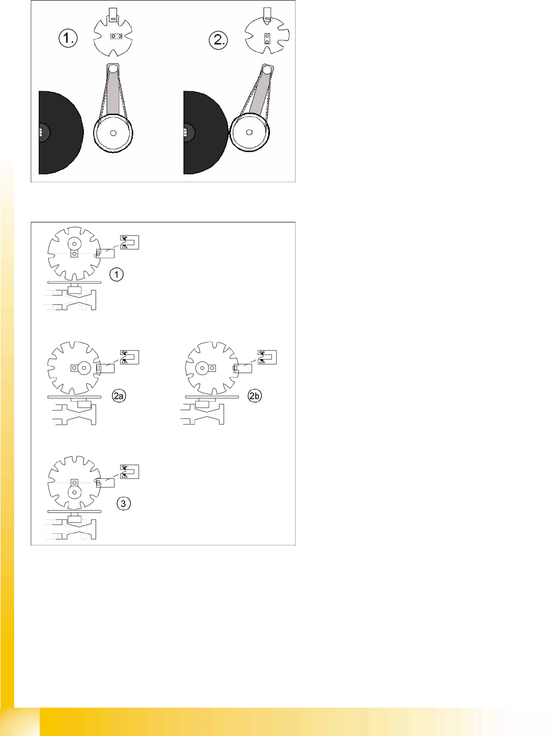
5-2: Initializing valve positioning drive at pickup/placement and reject position
Legend
1. Home position, initial position. Give way free
for Star axis movement.
or
3. Counter position to initial position. Give way
free for Star axis movement.
– The stepping motor of the valve
positioning drive is turned to the home
position. The stepping motor runs and the
light barrier on the cam disk sets the end
signal.
– Because of the special shape of the cam
disk, the stepping motor is able to
recognize the home position (1) or (3).
The valve positioning drives have positioned
the drive ball bearings in the valve plunger so
that star rotation without malfunction is
possible.
Reference Run
Axis Reference Run Reference Run (D-Series)
Student Guide Advanced Level 1 SIPLACE D-Series
EN 05/2007 Reference Run
5-3
X Star axis reference run
The following steps are performed in sequence:
– In the first reference run, the star axis performs a commutation point search for the 3-phase system
of the drive.
– The star axis positions itself at the axis zero pulse.
– The star axis loads the zero point correction value.
– The star axis positions itself at counter status 0. Segment 1 is now in the star pickup/placement
position.
X Z-axis reference point run
As the Z-axis does not have a zero pulse, the Z-axis end stopper is used for this "zero pulse position".
The zero point correction (ZPC) is determined during each reference run.
– The Z-axis moves again to the top end stopper and then positions itself to the standard value of 5
digits. Subsequently:
– The star axis positions to 6250 digits (6.25°).
– The Z-axis moves down again to the end stopper, transmits the Z-axis position and moves back to
the 5 digit position.
– The star axis positions to 6750 digits (6.75°).
– The Z-axis moves up again to the end stopper, transmits the Z-axis position and moves back to
the 5 digit position.
– The star axis positions to -6250 digits (-6.25°).
– The Z-axis moves down again to the end stopper, transmits the Z-axis position and moves back to
the 5 digit position.
– The star axis positions to -6750 digits (-6.75°).
– The Z-axis moves up again to the end stopper, transmits the Z-axis position and moves back to
the 5 digit position.
X The zero point correction value is calculated from the 4 Z-axis positions, is transmitted to the axis
controller and is used until the machine is switched off.
– The star axis is moved back to the 0 position (segment 1 down).
This automatic zero point correction ensures that the segment ball bearing is in the optimum position
for the circular guide.
X The head axis reference run is now finished.
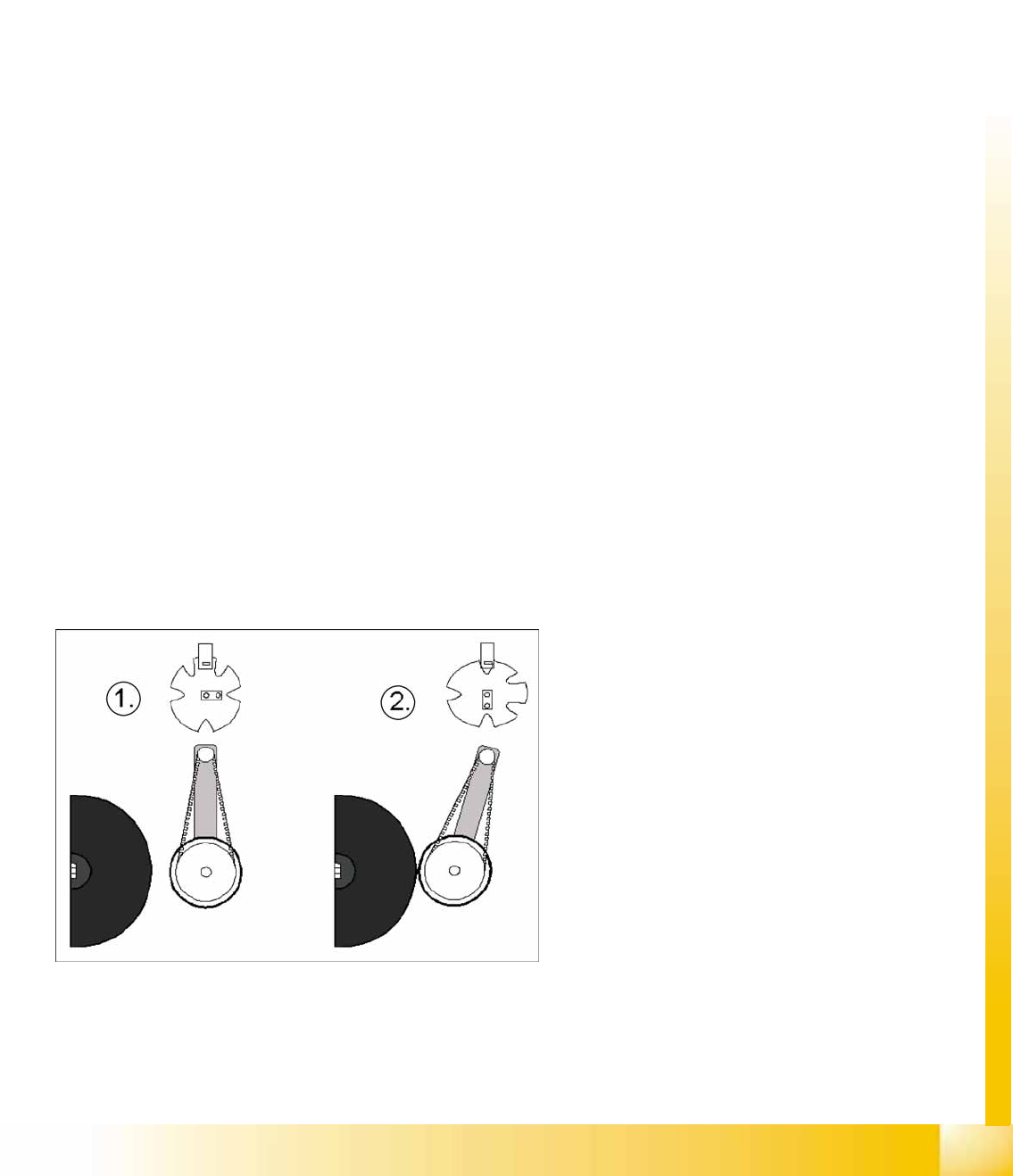
5-3: Positioning the DP axis with the help of the swivel in/out function
Legend
1. Home position of DP drive around 1 mm away
from segment.
2. Engaged position of DP drive at segment
X DP axis reference run
– The DP station is swiveled in by a CAN bus
command (2).
– The axis controller starts from the 0 position
and continues until the incremental encoder
detects a segment zero pulse.
X – The DP station is swiveled out again by a
CAN bus command (1).