D-serie level 1 EN.pdf - 第74页
Reference Run Reference Run (D-Series) Vacuum Reference Run S tuden t Guide Advanced Level 1 SIPLACE D-Series Reference Run EN 05/2007 5-6 5.1.4.2 Determining the V acuum and Threshold V alues 5-6: Measuring and calculat…
Reference Run
Vacuum Reference Run Reference Run (D-Series)
Student Guide Advanced Level 1 SIPLACE D-Series
EN 05/2007 Reference Run
5-5
5.1.4 Vacuum Reference Run
5.1.4.1 Nozzle Cleaning, Followed by Vacuum Measurement
The vacuum values "open" and "closed" can only be measured if the nozzles have been cleaned by air
blast to remove any contaminants.
Sequence:
X The gantry axes move the placement head to the reject position.
X The star rotates in an anticlockwise direction to move all segments through the working positions.
X The electromagnetic valve is activated in a cycle for "reject component" and "clean nozzle".
X The vacuum "open" and "closed" placement values are measured for the nozzle types.
Should an error occur, this means that the nozzle opening is too small or that the vacuum duct is
blocked. --> exchange the nozzle.
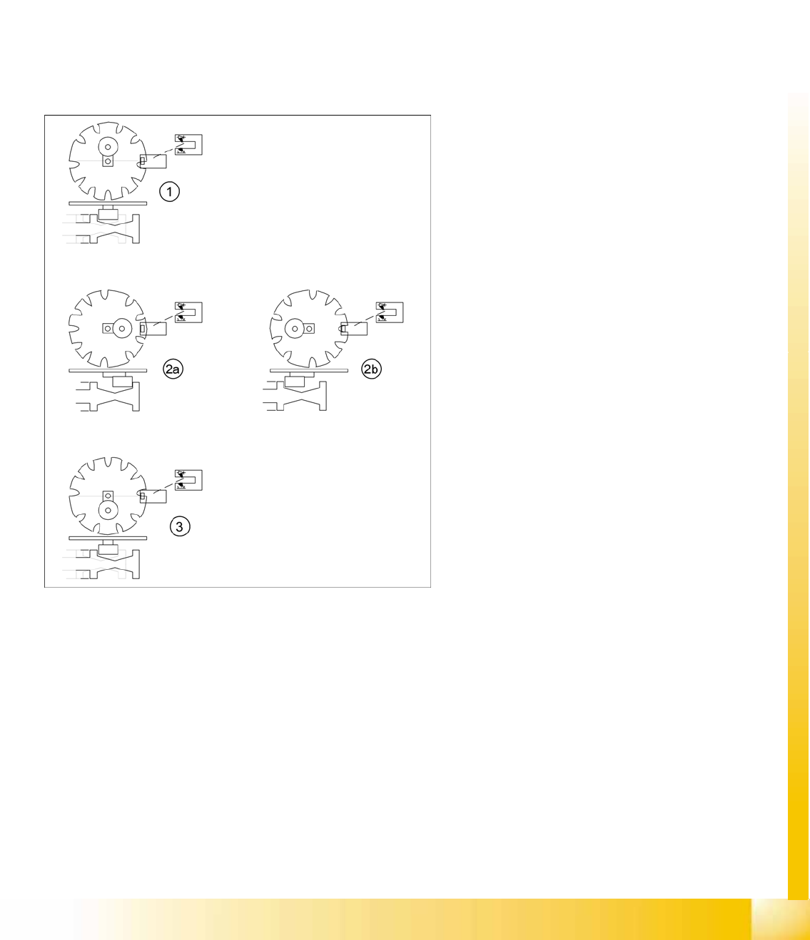
5-5: Switching over the valve positioning drives for pickup/place and reject
positions
Legend
1. Starting position. Give way free for Star axis
movement.
2. 2a: The mode "Valve positioning drive pick/
place" is switched to vacuum for "nozzle
open".
2b: The mode "valve positioning drive pick/
place" is switched to vacuum for "nozzle
closed". Parallel to this (diagram 2b) the "valve
positioning drive reject" is switched back to air
blast (and then back again).
3. Counter position to initial position. Give way
free for Star axis movement.
– The stepping motor of the valve
positioning drive is turned to the home
position. The stepping motor runs and the
light barrier on the cam disk sets the end
signal.
– Because of the special shape of the cam
disk, the stepping motor is able to
recognize the home position (1) or (3).
Reference Run
Reference Run (D-Series) Vacuum Reference Run
Student Guide Advanced Level 1 SIPLACE D-Series
Reference Run EN 05/2007
5-6
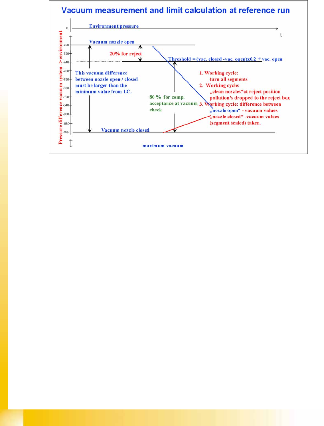
5.1.4.2 Determining the Vacuum and Threshold Values
5-6: Measuring and calculating the vacuum values for a reference run
Legend
1. The vacuum is measured twice during the reference run:
– Once with closed
– and once with open valve, while air flows through the nozzle.
2. The value with closed valve depends on the ambient pressure and may vary, according to the local
weather conditions and altitude. The higher the ambient pressure, the lower the vacuum at closed
valve.
3. The value with open valve depends on the nozzle size and condition. The smaller the nozzle, the
greater the open valve value will be. A contaminated or blocked nozzle will also give a higher valve.
4. The difference between the open and closed nozzles has been preset by the line controlling line
computer (LC or SIPLACE Pro), as a minimum value. This value is different for all nozzle types e.g.
120 mbar for 914 and 904 nozzles. If these values are not achieved, the error message
"Vakuumdifferenz offen-geschlossen zu gering" (vacuum difference open-closed is too low) will
appear.
5. The threshold for component acceptance is also set now. In this case we have a value of 700 mbar
when the nozzle is open and a value of 900 mbar when the nozzle is closed. The calculation is
performed as follows:
Threshold = (900(closed) - 700(open))= x 0.2 + 700(open) = 200 x 0.2 + 700 = 740

Reference Run
Height Reference Run Reference Run (D-Series)
Student Guide Advanced Level 1 SIPLACE D-Series
EN 05/2007 Reference Run
5-7
5.1.4.3 Rotating the Nozzles into the 0 Degrees Starting Position
While the vacuum values are being measured, the turning station can rotate all segment sleeves into the
0° starting position.
Sequence:
X The star axis rotates all segments through the working positions.
X The turning station swivels in during vacuum measurement.
X The axis controller positions the relevant segment at the light-dark transition, which represents the
0 degrees position of the sleeves. (The long side of rectangular nozzles in the X direction.)
X – The turning station is swiveled out again by a CAN bus command .
5.1.4.4 Nozzle Scanning
While the vacuum values are measured, the camera tests the empty nozzles for contaminants.
Sequence:
X The star axis rotates all segments through the working positions.
X The component camera illuminates the nozzle and measures its outer and inner contours.
X If the nominal dimensions are not met, a "nozzle dirty" error message is issued.
The vacuum reference run is now finished.
5.1.5 Height Reference Run
5.1.5.1 Head Height Check and Nozzle Length Measurement
This part of the reference run is performed in sequence at the gantries of the relevant processing area,
as the X/Y height measurement position needs to be the same for both gantries.
Sequence:
X The gantry axes move the placement head over the height measurement position on the fixed
conveyor side.
X The Z-axis moves segment 1 down, as far as the end stopper.
X The Z.axis "height position" is read out of the Z-axis position counter.
X The Z-axis is moved up again, to the 0 position.
X This process is repeated for all the segments of the relevant placement head and then for the 2nd
gantry.
X A nozzle length error is issued if the values deviate by more than+/- 0.4 mm from the nozzle 1
measurement. The nozzle causing this error must then be replaced before starting placement
operations.
NOTE:
All measurement values are accepted for special nozzles in the X9X series.