D-serie level 1 EN.pdf - 第78页
Reference Run P&P Reference Run Vacuum Check S tuden t Guide Advanced Level 1 SIPLACE D-Series Reference Run EN 05/2007 5-10 5.2.3 V acuum Check After the CAN bus proces sor for the va cuum/air bla s t generator ha…
Reference Run
Z-Axis Reference Run P&P Reference Run
Student Guide Advanced Level 1 SIPLACE D-Series
EN 05/2007 Reference Run
5-9
5.2 P&P Reference Run
5.2.1 Z-Axis Reference Run
5.2.2 D-Axis Reference Run
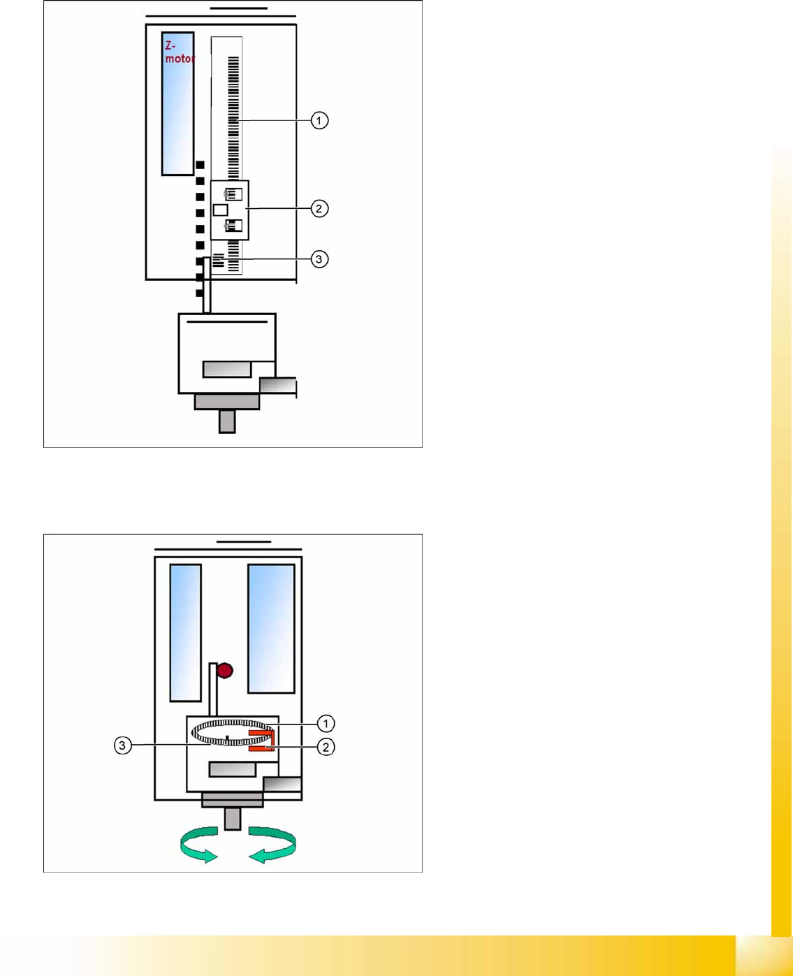
5-8: Z-axis reference run
Legend
1. Incremental scale mounted on moveable part
of the Z-Axis
2. Fixed incremental encoder
3. Zero pulse on the incremental scale (only one
for Z-axis)
Z-axis search for the commutation point of the
linear motors in a special mode. (A 3 phase
motor continues to run at the correct time and
in the correct sequence, when the current is
switched from 1 phase to the next one.)
Then the Z-axis moves upwards to the zero
pulse and loads the zero point correction.
The zero point correction, max. and min. travel
range, are determined when you calibrate the
head height.
5-9: D-axis reference run
Legend
1. Incremental glass scale for D-axis
2. Incremental encoder
3. Zero pulse on incremental glass scale
The D-axis (turning axis) then performs a
reference run.
The D-axis moves to the zero pulse of the D-axis
incremental encoder. The zero point correction is
loaded. The D-axis moves to the reference
position, in accordance with the polarity.
Reference run finished! The gantry reference
run (see Section Gantry) follows.
Reference Run
P&P Reference Run Vacuum Check
Student Guide Advanced Level 1 SIPLACE D-Series
Reference Run EN 05/2007
5-10
5.2.3 Vacuum Check
After the CAN bus processor for the vacuum/air blast generator has booted, this is initialized. This
means that the vacuum/air blast generator is regulated to ensure that neither vacuum or air blast is
generated at the nozzle.
The gantry axes move the Twin head to the reject position.
When the head is over the reject container, the vacuum/air blast generator switches over to air blast,
to reject components and check the air blast.
The vacuum/air blast generator now switches to vacuum and the open vacuum is measured* for both
segments (X and D3 machines, D1: one Twin segment).
After measurement, the pressure is regulated to 0 bar.
The vacuum reference run for the Twin head is now finished.
* The closed vacuum value for the Twin segments relates to the calibration value, which is determined
in SITEST.
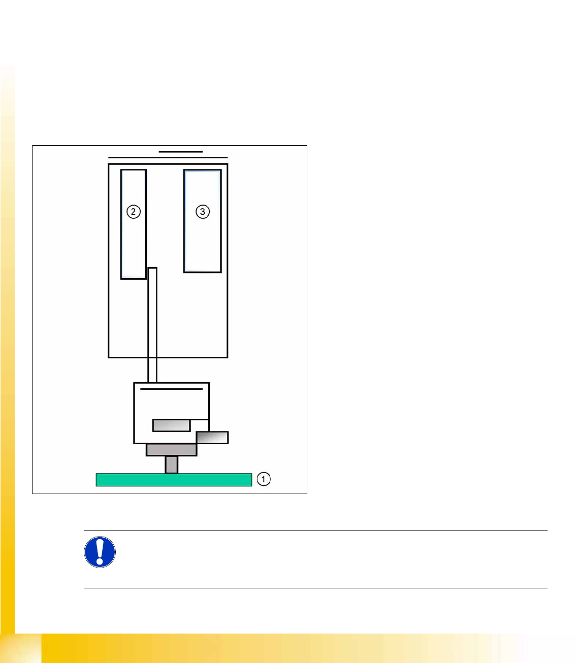
5.2.4 Height Reference Run
5-10: Measuring the nozzle height
This function checks whether the correct,
programmed nozzle type is used. The nozzle
length is taken to calculate the pick up, centering
and placement height for the following
placements.
Legend
1. Top of fixed conveyor side
2. Z-motor
3. Vacuum - air blast distribution
X The gantry moves the placement heads above
the fixed conveyor side.
X The Z-axis positions module 2 (X/D3 machine)
downwards.
X The travel range of the Z-axis is taken to
calculate the TWIN Head height in relation to
the nozzle type.
X The same procedure is now performed for
module 1.
X The maximum length tolerance is 0.4 mm: If
the length difference is too high an error
message is displayed.
NOTE:
Both modules are measured at the same position of the PCB conveyor!
This TWIN Head reference run is performed parallel to the C&P head reference run in the other
placement area.

Reference Run
Height Reference Run Room for Your Sketches and Notes
Student Guide Advanced Level 1 SIPLACE D-Series
EN 05/2007 Reference Run
5-11
5.3 Room for Your Sketches and Notes