D-serie level 1 EN.pdf - 第88页
C&P6/12 Placement Heads Overview Compressed Air Supply on C&P Head S tuden t Guide Advanced Level 1 SIPLACE D-Series C&P6/12 Placement Heads EN 05/2007 6-8 6.1.6 Compressed Air Supply on C&P Head The comp…
C&P6/12 Placement Heads
C&P Head Placement Construction Overview
Student Guide Advanced Level 1 SIPLACE D-Series
EN 05/2007 C&P6/12 Placement Heads
6-7
6.1.5.6 Nozzle Changer for 12 Segment C&P Head
Optionally, a nozzle changer can be installed for each C&P head. This enables the nozzle configuration
to be changed quickly, thus allowing the Collect&Place head to be quickly adapted to the needs of the
placement process.
The nozzle changer consists of at least one and up to five magazines, each of which is equipped with
up to twelve nozzle garages. The magazines are seated on a common support and each magazine is
centered using two pins and is fixed in place with a spring hook.
Each garage can be configured with different nozzle types.
Features for C&P6
head
D4 D3 D2 D1
Number of NC
carriers per gantry
--- 2 X compatible 1 new 1 new
Number of
magazines per
carrier
--- 6 6 6
Length of NC carrier
(outer edges)
475 mm 450 mm 565 mm 565 mm
Features for C&P12 D4 D3 D2 D1
NC features for C&P placement head
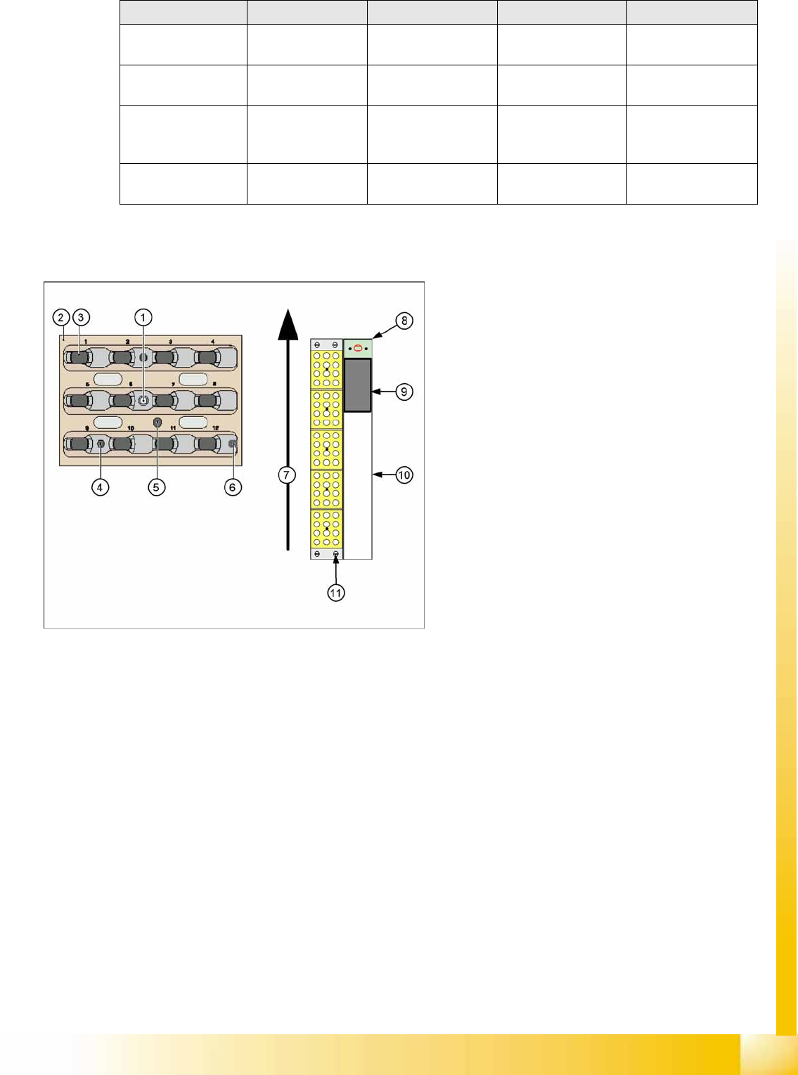
6-4: Nozzle changer and nozzle magazine for C&P12 (D4 shown as
example)
Legend
1. Calibration fiducial on magazine
2. Locking plate
3. Nozzle garage
4. Hole for centering pin, for exact positioning of
magazine
5. Hole for driver pin, for opening and closing of
magazine
6. Slit for centering pin, for exact positioning of
magazine
7. Transport direction
8. Nozzle reject device
9. Nozzle reject container
10. Tape duct
11. Fastening screws for nozzle changer (4x)
C&P6/12 Placement Heads
Overview Compressed Air Supply on C&P Head
Student Guide Advanced Level 1 SIPLACE D-Series
C&P6/12 Placement Heads EN 05/2007
6-8
6.1.6 Compressed Air Supply on C&P Head
The compressed air for D1/2 machines is distributed via an additional T-piece and small component sets
with pneumatic hoses to the two placement heads.
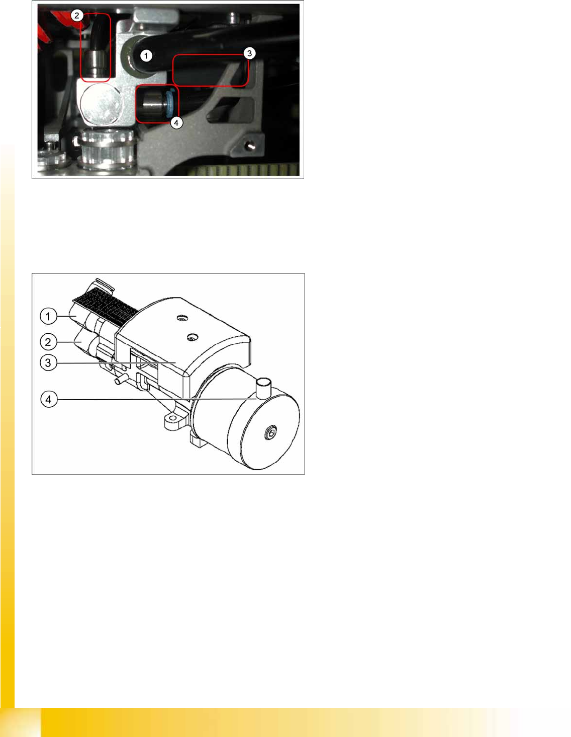
6.1.6.1 Vacuum Generator
6-5: Pneumatic distributor under the gantry head distributor
Legend
1. Input: Exhaust Venturi nozzle pneumatic hose
(PK12)
2. Input: 7-fold pneumatic hose (PK 5)
3. Silencer for exhaust (indicated in the diagram)
4. Compressed air outlet for pickup/placement
circuit and holding circuit
D1/2: to T distributor C&P/P&P head
D4: to C&P head
6-6: Vacuum generator
Legend
1. Holding circuit supply
2. Placement and pickup circuit with branching
for air blast supply
3. Vacuum measuring board
4. Exhaust from the vacuum generator to the
silencer in the compressed air distributor

C&P6/12 Placement Heads
Service Work on C&P Head - Details Overview
Student Guide Advanced Level 1 SIPLACE D-Series
EN 05/2007 C&P6/12 Placement Heads
6-9
6.1.7 Service Work on C&P Head - Details
Service work
Chapter "C&P6/12" of the service manual explains the service work in detail, in the following order:
Replacing the C&P6/12 head - D1 D2
Replacing the front part
Replacing the component camera
Replacing the intermediate distributor
Replacing the turning station
Replacing the valve positioning drive, placement circuit
Replacing the valve positioning drive, reject circuit
Replacing the "Z-axis up" light barrier
Replacing the Z-axis drive
Replacing the Z-axis toothed belt
Replacing the "Z-axis down" sensor
Replacing the complete Z-axis
Replacing the forced air unit
Replacing the silencer
Replacing the star
– Adjusting the star to the magnetic neutral position of the star motor
Replacing the star drive
Replacing the RSF digital rotary encoder
Replacing the control board for the nozzle changer 6/12
Checking the cable routing (DLM3)
Settings
The chapter "Settings" of the service manual explains the settings for the C&P6/12 head in detail:
Boards on the C&P6/12
Overview of settings for C&P12 (DLM3)
Setting the star axis resolution
Digital rotary encoder for the DP axis
Z-axis belt tension
Setting the Z-axis top end stopper
Light barrier down
Determining the zero point correction for the C&P head star axis
Setting the valve positioning drives for the mechanical position
Air blast values
Other mechanical settings for the placement star