D-serie level 1 EN.pdf - 第91页
C&P6/12 Placement Heads Overview Vacuum Supply Overview S tude nt Guide Advanced Level 1 SIPLACE D-Series EN 05/2 007 C&P6/12 Placement Heads 6-1 1 6.1.9 Overview V acuum Su pply 6-8: Overview of vacuum function
C&P6/12 Placement Heads
Overview Overview Air Blast Supply
Student Guide Advanced Level 1 SIPLACE D-Series
C&P6/12 Placement Heads EN 05/2007
6-10
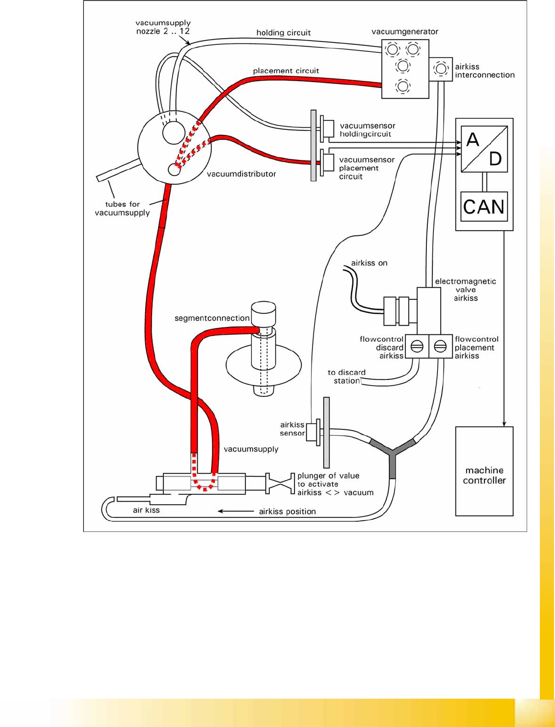
6.1.8 Overview Air Blast Supply
6-7: General overview of the air blast function
C&P6/12 Placement Heads
Overview Vacuum Supply Overview
Student Guide Advanced Level 1 SIPLACE D-Series
EN 05/2007 C&P6/12 Placement Heads
6-11
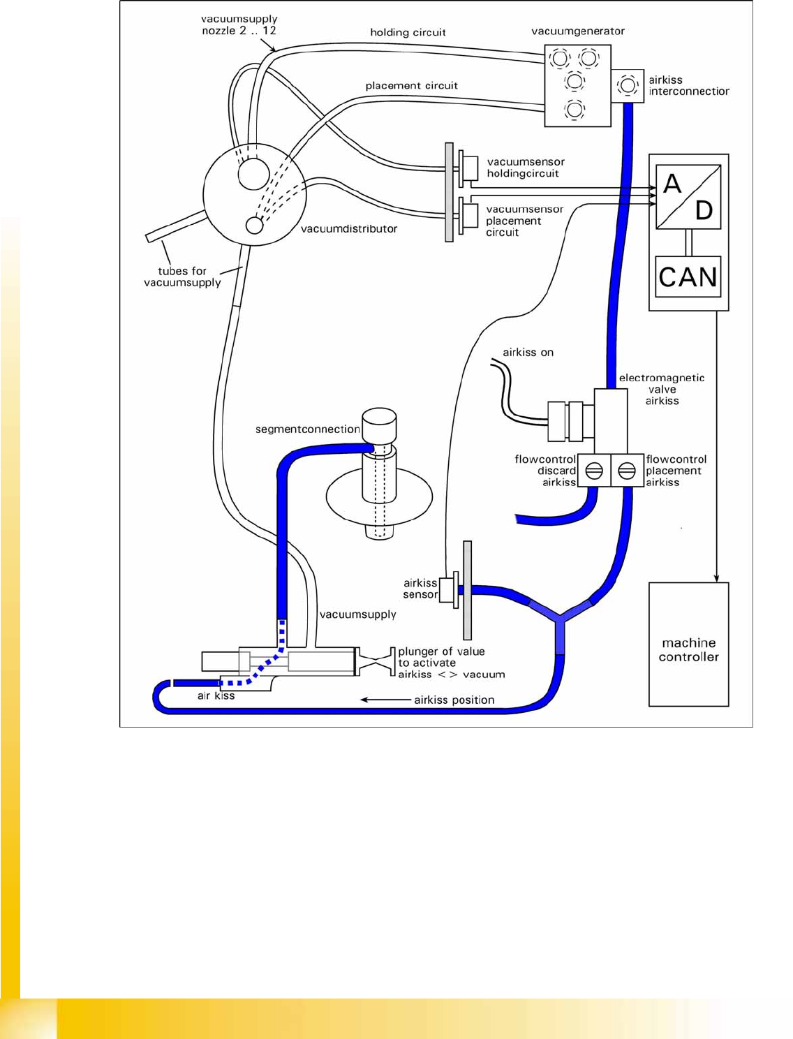
6.1.9 Overview Vacuum Supply
6-8: Overview of vacuum function
C&P6/12 Placement Heads
Placement Procedure Air Blast and Vacuum Supply - Description
Student Guide Advanced Level 1 SIPLACE D-Series
C&P6/12 Placement Heads EN 05/2007
6-12
6.1.10 Air Blast and Vacuum Supply - Description
The two diagrams show that there are 3 states for air supply to the segments.
Electromagnetic valves ON & valve plunger inside: air blast is present at the segment for placement
(reject).
Electromagnetic valves OFF & valve plunger inside: the segment is airtight i.e. it is cut off from the
air blast and vacuum supplies.
Valve plunger pulled (towards back): the connection to the vacuum supply exists, even if the
electromagnetic valve is switched on.
This function description illustrates that the valve plunger is the element with the greatest influence on
the placement and pickup reliability. It is therefore important to maintain this key part with the tools
specially developed for this purpose.
6.2 Placement Procedure
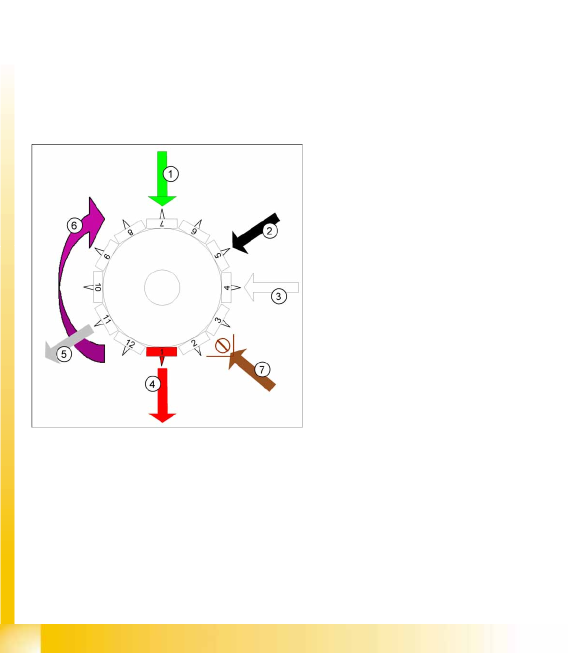
6.2.1 Working Position on Placement Head
6-9: Working position on placement head
Legend
1. optical centering
2. Turning station / DLM2
3. Service position for segment: check/remove
the nozzles and sleeves
4. Pickup and placement station (reject station
for D1/D2 and D3)
5. Reject position for D4 machines
6. Direction of operation
7. Position of component sensor option (only
C&P12)