OM-1650-001_w - 第12页
OM-1650 9 6. Pattern Program Unit PCB BBR [1] Mode Set one of the following options to determine whether or not the unit PCB BBR detection (bad board reject) function should be used. Disable : The unit PCB BBR detection …
OM-1650
8
6. Pattern Program
6. Pattern Program
6.1 Operation Data
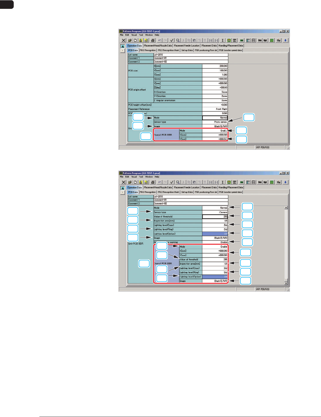
Open the "PCB Data" tab sheet in "Operation Data" and edit the "Unit PCB BBR"
data.
[1]
[2]
[3]
[10]
(1)
(2)
Sensor Type: Photo-Sensor F4
[1]
[3]
[5]
[7]
[9]
[2]
[4]
[6]
[8]
[10]
(1)
(3)
(5)
(7)
(4)
(2)
(6)
(8)
Sensor Type: Camera F5
1006-001

OM-1650
9
6. Pattern Program
Unit PCB BBR
[1] Mode
Set one of the following options to determine whether or not the unit PCB
BBR detection (bad board reject) function should be used.
Disable
: The unit PCB BBR detection function is disabled.
Normal
: The unit PCB BBR detection is made at the standard position.
Optional
: The unit PCB BBR detection is made at an optional position.
Reference
(a) Refer to "6.2 Placement Data (P-Data)" for the standard position
details.
(b) Refer to "6.3 Placement Data (O-Data)" for the optional position
details.
[2] Sensor Type
Select either "Photosensor" or "Camera" in this text box.
Photosensor
: The bad mark sensor is used.
Camera
: The PEC recognition camera is used.
[3] Value of threshold
Set the threshold value for bad mark detection in this text box.
•
Data Input Range:
1 to 255
Reference
Refer to "9. Bad Mark Camera Test" for the threshold value.
[4] Inspection Area [mm]
Set the area for the PEC recognition camera to detect a bad mark in this text
box.
•
Data Input Range:
0.1 to 1.0
[5] Lighting Level (Coax)
Select the brightness level (one of the options described below) of the coaxial
lighting for the PEC recognition camera in this text box.
[Std], [-80%], [-60%], [-40%], [-20%],
[+20%], [+40%], [+60%], [+80%], [Off]
1006-001

OM-1650
10
6. Pattern Program
[6] Lighting Level (Ring)
Select the brightness level (one of the options described below) of the ring
lighting for the PEC recognition camera in this text box.
[Std], [-80%], [-60%], [-40%], [-20%],
[+20%], [+40%], [+60%], [+80%], [Off]
[7] Lighting Level (Option)
Select the brightness level of the optional lighting level for the PEC
recognition camera in this text box.
[Std], [-80%], [-60%], [-40%], [-20%],
[+20%], [+40%], [+60%], [+80%], [Off]
[8] Image
Set the bad mark image.
Black (E/NR (Light Emitted and Not Received)):
A black mark (E/NR) is used.
White (E/R (Light Emitted and Received)):
A white mark (E/R) is used.
[9] Boundary value warning
When the detected bad mark is in the range of ±5 (gray value) in comparison
with the threshold value for judgment or meets the threshold value, the
machine stops in an error condition.
After the error stop condition is recovered, specify if a bad mark exists or not
for each unit PCB in the "Manual Alignment" window.
Enable
: The boundary value warning function is used.
Disable
: The boundary value warning function is not used.
1006-001