OM-1650-001_w - 第13页
OM-1650 10 6. Pattern Program [6] Lighting Level (Ring) Select the brightness level (one of the options described below) of the ring lighting for the PEC recognition camera in this text box. [Std], [-80%], [-60%], [-40%]…

OM-1650
9
6. Pattern Program
Unit PCB BBR
[1] Mode
Set one of the following options to determine whether or not the unit PCB
BBR detection (bad board reject) function should be used.
Disable
: The unit PCB BBR detection function is disabled.
Normal
: The unit PCB BBR detection is made at the standard position.
Optional
: The unit PCB BBR detection is made at an optional position.
Reference
(a) Refer to "6.2 Placement Data (P-Data)" for the standard position
details.
(b) Refer to "6.3 Placement Data (O-Data)" for the optional position
details.
[2] Sensor Type
Select either "Photosensor" or "Camera" in this text box.
Photosensor
: The bad mark sensor is used.
Camera
: The PEC recognition camera is used.
[3] Value of threshold
Set the threshold value for bad mark detection in this text box.
•
Data Input Range:
1 to 255
Reference
Refer to "9. Bad Mark Camera Test" for the threshold value.
[4] Inspection Area [mm]
Set the area for the PEC recognition camera to detect a bad mark in this text
box.
•
Data Input Range:
0.1 to 1.0
[5] Lighting Level (Coax)
Select the brightness level (one of the options described below) of the coaxial
lighting for the PEC recognition camera in this text box.
[Std], [-80%], [-60%], [-40%], [-20%],
[+20%], [+40%], [+60%], [+80%], [Off]
1006-001

OM-1650
10
6. Pattern Program
[6] Lighting Level (Ring)
Select the brightness level (one of the options described below) of the ring
lighting for the PEC recognition camera in this text box.
[Std], [-80%], [-60%], [-40%], [-20%],
[+20%], [+40%], [+60%], [+80%], [Off]
[7] Lighting Level (Option)
Select the brightness level of the optional lighting level for the PEC
recognition camera in this text box.
[Std], [-80%], [-60%], [-40%], [-20%],
[+20%], [+40%], [+60%], [+80%], [Off]
[8] Image
Set the bad mark image.
Black (E/NR (Light Emitted and Not Received)):
A black mark (E/NR) is used.
White (E/R (Light Emitted and Received)):
A white mark (E/R) is used.
[9] Boundary value warning
When the detected bad mark is in the range of ±5 (gray value) in comparison
with the threshold value for judgment or meets the threshold value, the
machine stops in an error condition.
After the error stop condition is recovered, specify if a bad mark exists or not
for each unit PCB in the "Manual Alignment" window.
Enable
: The boundary value warning function is used.
Disable
: The boundary value warning function is not used.
1006-001
OM-1650
11
6. Pattern Program
[10] Overall PCB BBR
(1) Mode
Select one of the following options for the overall PCB BBR function.
Disable
: The overall PCB BBR detection function is not used.
Enable
: The overall PCB BBR detection function is used.
(2) X [mm], Y [mm]
When "Enable" is selected in the "Mode" text box, the coordinates (X
and Y) of the bad mark should be set for the overall PCB BBR detection
function.
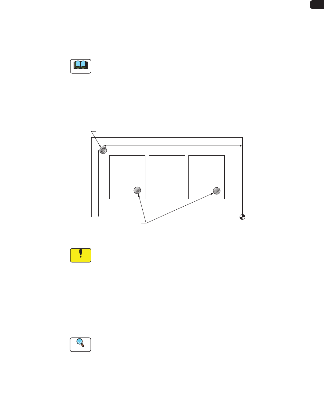
Note
Overall PCB BBR Detection Function
When there are a few unit PCB's with a bad mark and most of the unit
PCB's are of good quality, then use the overall PCB BBR function.
Before a bad mark detection for each unit PCB, perform overall PCB BBR
detection. If any bad mark is not detected in overall PCB BBR detection,
then all the unit PCB's are regarded as good PCB's and the unit PCB BBR
detection is not performed.
Placement Coordinate Reference (No)
X (Horizontal)
Y (Vertical)
Bad Mark for Overall PCB BBR Function
Bad Marks
F6
Notice
When this function is set to "Enable", all the PCBs without a master
bad mark, are processed as good PCBs.
When a bad mark has been placed on any unit PCB, take care not
to forget placing a master bad mark.
(3) Value of threshold
Set the threshold value for bad mark determination.
•
Data Input Range:
1 to 255
Reference
Refer to "9. Bad Mark Camera Test" for the threshold value.
(4) Inspection Area [mm]
Set the area for the PEC recognition camera to detect a bad mark.
•
Data Input Range:
0.1 to 1.0
1006-001