OM-1650-001_w - 第21页
OM-1650 18 8. Procedure for Bad Mark Sensor Adjustment (10) Press the [Bad mark detection pos. move (White Part)] button and press the [ST AR T] button on the operation panel. (The head will move to the bad mark detectio…
OM-1650
17
8. Procedure for Bad Mark Sensor Adjustment
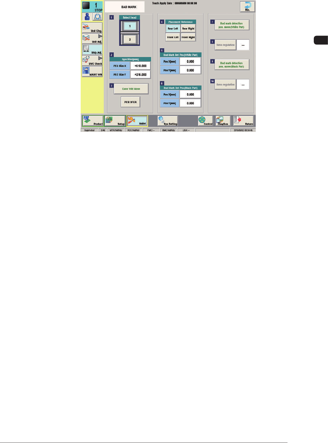
(4) Open the "BAD MARK" window in the "Ship. Adj." window in the "Maint."
menu.
F13
(5) Select the head for which the sensitivity should be adjusted with the related
head selection button.
(6) The "Placement Reference" is the same as that for the pattern program set as
the current program.
(7) Confirm the PEC (PCB) size "X" and "Y" in the "Specified [mm]" data
boxes.
(8) Enter the parameters for the white bad mark position in the "Pos X [mm]"
and "Pos Y [mm]" text boxes for the "Bad Mark Det Pos (White Part)".
(9) Enter the parameters for the black bad mark position in the position "Pos
X [mm]" and "Pos Y [mm]" text boxes for the "Bad Mark Det Pos (Black
Part)".
1006-001

OM-1650
18
8. Procedure for Bad Mark Sensor Adjustment
(10) Press the [Bad mark detection pos. move (White Part)] button and press the
[START] button on the operation panel.
(The head will move to the bad mark detection position (white part)).
(11) Press the [Sens regulation] button.
(12) Press the cover lock switch and open the transparent covers on the upper
section of the beam.
(13) Confirm that the tuning indicator LED (yellow) of the amplifier is ON.
(14) Close the cover and press the Cover Lock switch.
(15) Press the [Bad mark detection pos. move (Black Part)] button and press the
[START] button on the operation panel.
(The head will move to the bad mark detection position (black section)).
(16) Press the newly selectable [Sens regulation] button.
(17) Use several PCBs to be produced to check if the bad mark sensor works
normally.
1006-001
OM-1650
19
9. Bad Mark Camera Test
9. Bad Mark Camera Test
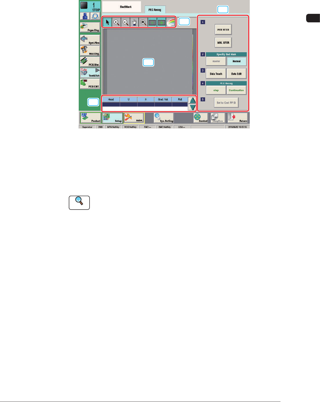
When the camera system is used in the bad mark detection function, the
"Threshold" is calculated to set the "Value of threshold" on the "PCB Data" sub-
tab sheet on the "Operation Data" tab sheet.
[1]
[3]
[2]
[4]
F14
[1] Displayed Image Operation Button
Using the following buttons, the modes for performing the enlarging or
movement operation for the image displayed in the recognition image display
pane [2], are changed.
Reference
Refer to "7. Test and Teaching" in Chapter 6 in Volume 2 in the
SIGMA-G4/G5 Instruction Manual for the displayed image operation
buttons.
[2] Recognition Image Display Section
The recognition results are displayed in this section.
[3] Bad Mark Camera Test Measurement Results
The bad mark camera test measurement results are displayed in this section.
[4] Operation Buttons
Specify Bad Mark
[Master] Button
: This button is selected when the Master Bad
Mark Detection (Overall BBR Detection) is to be
performed.
[Normal] Button
: This button is selected when the normal BBR
detection (individual detection) is to be performed.
[Data Teach] Button
: This button is selected when the data teaching is to
be performed.
[Data Edit] Button
: This button is selected when the data editing is
performed.
1006-001