Void Reduction in Bottom Terminated Components Using Vacuum Assisted Reflow - 第2页
Figure 2- Straight Ramp Reflow Profil e Figure 3- Soak Reflow Profile The second reflo w profile recommendation is to minimize the p eak temperature since entrapp ed vapors will expan d with increasing temperatures. X-ra…
Void Reduction in Bottom Terminated Components Using Vacuum Assisted Reflow
M. Holtzer[2], M. Barnes[1], D.W. Lee[1], D. Heller[1], T. Cucu[2], J. Fudala[3], J. Renda[3],
[1] Heller Industries, Florham Park, New Jersey (USA)
MI. Alpha Assembly Solutions, South Plainfield, New Jersey (USA)
[3] MacDermid Enthone Electronic Solutions, West Haven, Connecticut (USA)
Abstract
Pockets of gas, or voids, trapped in the solder interface between discrete power management devices and circuit assemblies
are, unfortunately, excellent insulators, or barriers to thermal conductivity. This resistance to heat flow reduces the electrical
efficiency of these devices, reducing battery life and expected functional life time of electronic assemblies. There is also a
corresponding increase in current density (as the area for current conduction is reduced) that generates additional heat, further
leading to performance degradation.
This paper will describe the results of a series of experiments performed in an in-line convection reflow oven, using a typical
lead free reflow profile, with three types of bottom terminated components commonly used in power management
applications. A solder paste flux and alloy with a known high level of voiding was used as the control. This solder alloy is of
unique interest, despite its voiding in ambient reflow conditions, as it has shown superior resistance to failure under
automotive thermal cycling conditions (-40C to +125C) and vibration.
The experimental design was comprised of two levels of vacuum (5 and 20 torr) applied at two levels of time (30 seconds and
60 seconds) while the test assemblies were at or above the liquidus temperature of the lead free solder alloy. Each 2 x
2 factorial was performed on identical printed circuit boards with four (4) different substrate surface finishes,
including Immersion silver, Immersion tin, ENIG (Electroless nickel, Immersion gold) and an Organic Solder Preservative
(OSP) finish used. Each condition was repeated three times and three controls with no vacuum were also processed for
each surface finish. Therefore, a total of 60 component/substrate samples were processed and subsequently examined for
voiding using X-ray analysis.
The results of this study indicate that the vacuum pressure, time under vacuum and the surface finish have little effect on the
results when vacuum reflow is utilized. The use of a low pressure vacuum when the solder alloy is in liquidus conclusively
results in a significant reduction of observable voids in each combination of surface finish and reflow process condition.
Introduction
Studies to examine void reduction in lead-free Ball Grid Array (BGA) and Bottom Terminated Components (BTC) have been
reported for several years [1-5]. BGA voiding has been shown to be an easier problem to solve, using two basic techniques in
a conventional reflow oven. These have shown to be effective in dozens of field application case histories in reducing BGA
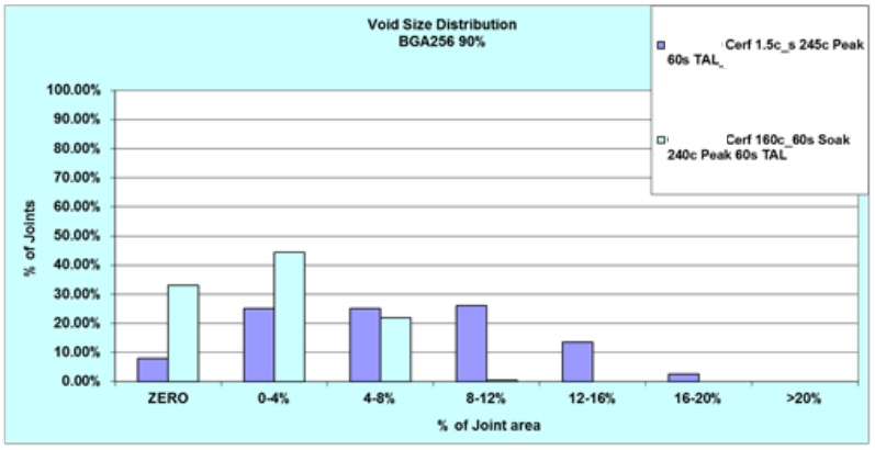
voiding. First, using a soak reflow profile typically reduces BGA voiding to acceptable levels versus a straight ramp profile.
(Figures 1-3)
Figure 1- Effect of Reflow Profile on BGA
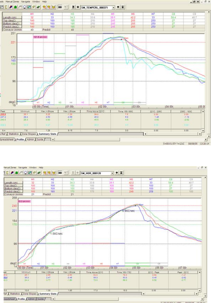
Figure 2- Straight Ramp Reflow Profile
Figure 3- Soak ReflowProfile
The second reflow profile recommendation is to minimize the peak temperature since entrapped vapors will expand with
increasing temperatures. X-ray videos have demonstrated this assertion is valid and does indeed promote BGA void
reduction. Another effective method for reducing BGA voiding is to minimize the volume of solder paste deposited, thereby
reducing the ratio of flux to metal in the BGA sphere/solder paste joint. Stencil design is the key to paste volume reduction.
BTC voiding is not as readily reduced with the same techniques. Video studies have shown that the time above liquidus can
greatly reduce voids since the gas bubbles in the liquid solder are mobile and governed by Brownian motion. Longer times
above liquidus allow more gas bubbles to reach the edges of the solder deposit where the bubble will disappear and not be
replaced.
To enhance this bubble movement effect, the application of vacuum to the solder joint while the solder is in its molten phase
has shown to be very effective in reducing BTC voids. The trapped gas bubbles expand under vacuum and are far more likely
to reach the edges of the solder deposit and disappear. The pressure inside trapped gas bubbles changes according to the
Young-Laplace Equation
P
bubble
= P
ambient
+ 2 / r
where is surface tension, r is the radius of the bubble and P
ambient
is the pressure in the vacuum reflow chamber. The reduced
pressure in the bubble, P
bubble,
can then used to determine the new bubble size according to the ideal gas law.
Methodology
In this study, a known high voiding solder paste flux and powder alloy combination was used [6]. Two vacuum pressures, 5
and 20 torr were used. Two vacuum dwell times, 30 and 60 seconds were also used, making the vacuum process a 2 x 2 full
factorial experimental design.
One production lot of a FR-4 test vehicle was produced, then split into 4 lots for copper surface finishing. 15 of the boards
were finished with electroless nickel, immersion gold (ENIG), 15 were finished with Immersion Tin, 15 with Immersion
Silver and 15 had an Organsic Surface Preservative (OSP) finish. The DOE called for 4 conditions, and 3 boards were used
for each condition, leaving 3 contingency test vehicles for each surface finish.
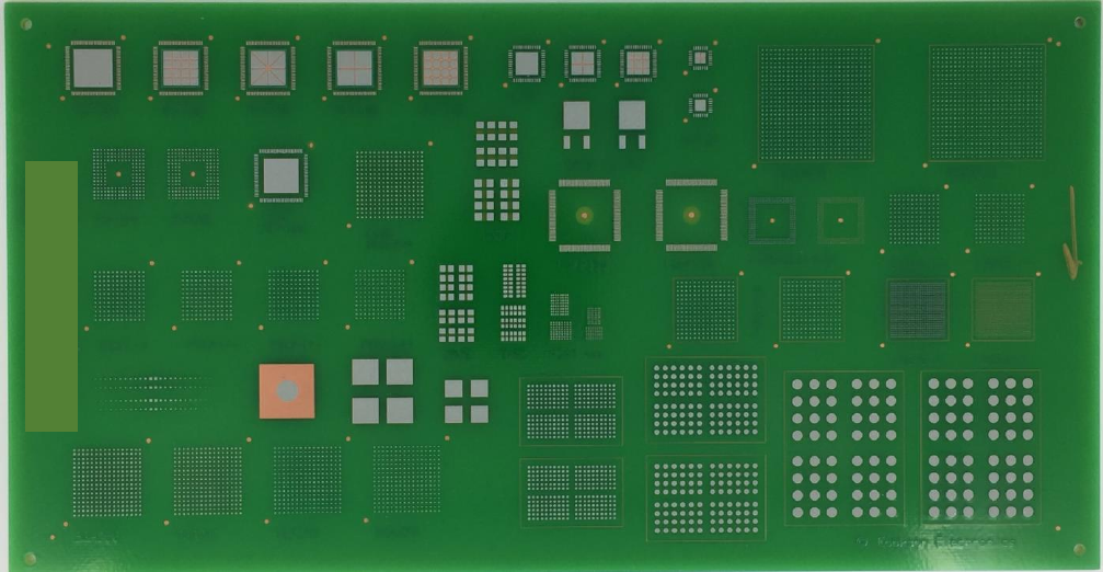
Several spare OSP boards were used to establish the desired reflow profiles. Figure 4 shows the unpopulated company test
vehicle which measured 25.4 x 13.3 x .24 cm (10 x 5.25 x .093 in.). Figure 5 shows the test vehicle populated with
components. The components included MLF 100s, DPAK TO-252s, BGA 256s, and LGA 228s,
Figure 4- Unpopulated Test Vehicle