Void Reduction in Bottom Terminated Components Using Vacuum Assisted Reflow - 第4页
Figure 5- Populated Test Vehicle Solder paste was pr inted us ing a 100µ m thick laser cut stainless steel ste ncil with no coating. Co mponents were p laced , then the assemblies w ere fed in to an air atm osphere , 8 z…
To enhance this bubble movement effect, the application of vacuum to the solder joint while the solder is in its molten phase
has shown to be very effective in reducing BTC voids. The trapped gas bubbles expand under vacuum and are far more likely
to reach the edges of the solder deposit and disappear. The pressure inside trapped gas bubbles changes according to the
Young-Laplace Equation
P
bubble
= P
ambient
+ 2 / r
where is surface tension, r is the radius of the bubble and P
ambient
is the pressure in the vacuum reflow chamber. The reduced
pressure in the bubble, P
bubble,
can then used to determine the new bubble size according to the ideal gas law.
Methodology
In this study, a known high voiding solder paste flux and powder alloy combination was used [6]. Two vacuum pressures, 5
and 20 torr were used. Two vacuum dwell times, 30 and 60 seconds were also used, making the vacuum process a 2 x 2 full
factorial experimental design.
One production lot of a FR-4 test vehicle was produced, then split into 4 lots for copper surface finishing. 15 of the boards
were finished with electroless nickel, immersion gold (ENIG), 15 were finished with Immersion Tin, 15 with Immersion
Silver and 15 had an Organsic Surface Preservative (OSP) finish. The DOE called for 4 conditions, and 3 boards were used
for each condition, leaving 3 contingency test vehicles for each surface finish.
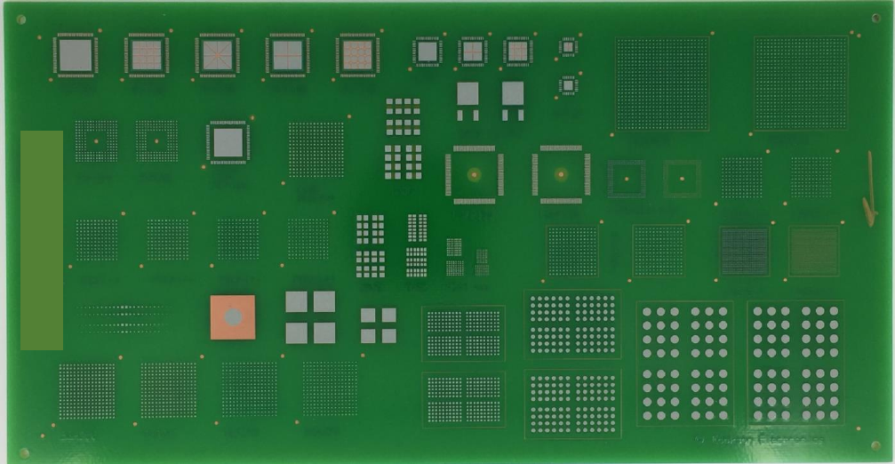
Several spare OSP boards were used to establish the desired reflow profiles. Figure 4 shows the unpopulated company test
vehicle which measured 25.4 x 13.3 x .24 cm (10 x 5.25 x .093 in.). Figure 5 shows the test vehicle populated with
components. The components included MLF 100s, DPAK TO-252s, BGA 256s, and LGA 228s,
Figure 4- Unpopulated Test Vehicle
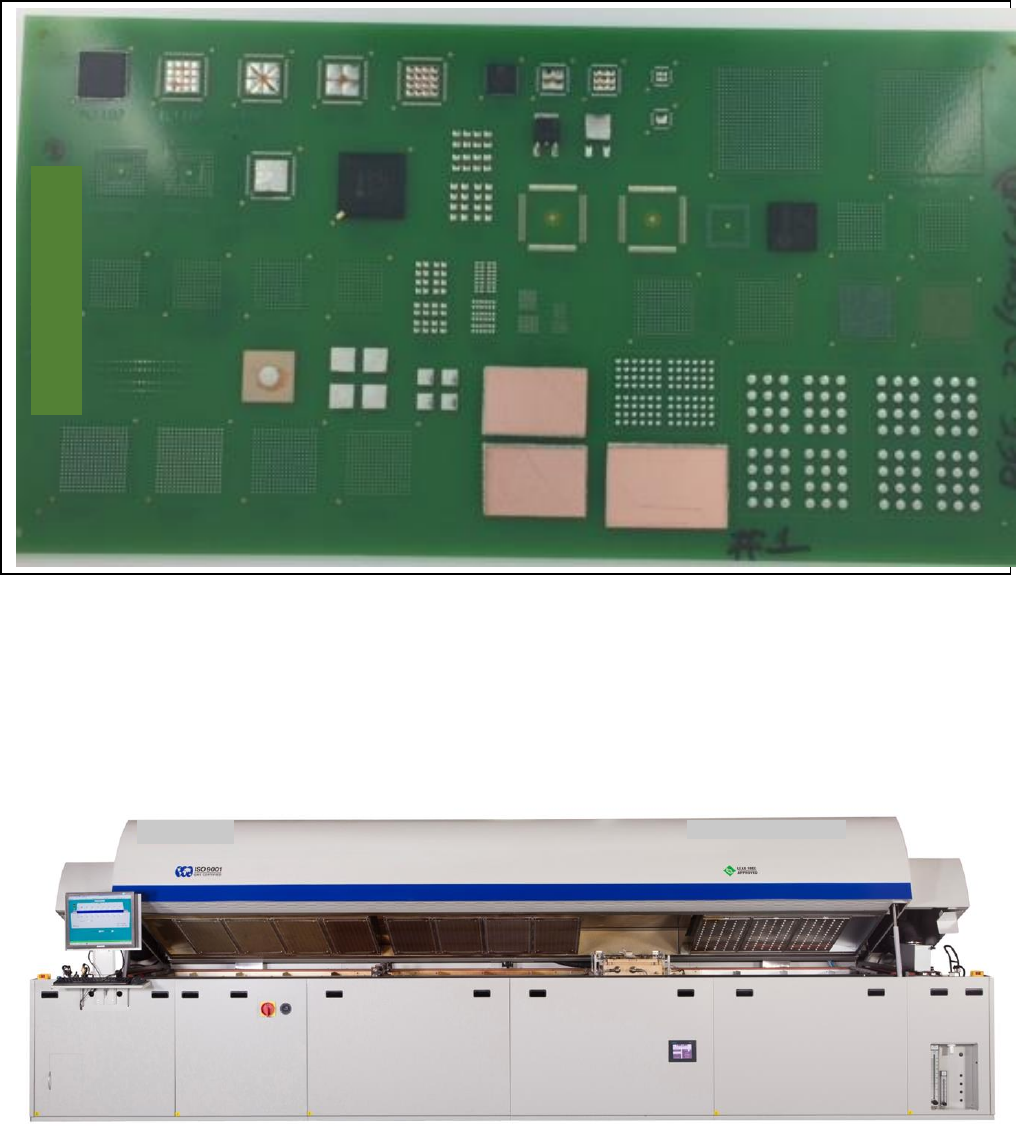
Figure 5- Populated Test Vehicle
Solder paste was printed using a 100µm thick laser cut stainless steel stencil with no coating. Components were placed, then
the assemblies were fed into an air atmosphere, 8 zone convection oven with a special vacuum chamber located after
convection zone 8 and before cooling zone 1. Two separate conveyors meet in this zone. As the assemblies reached the
chamber, the assembly is transferred onto the second conveyor which is not moving. The vacuum chamber closes, and air is
evacuated from the chamber. Figures 6 and 7 show the outline of the oven, and a close up of the vacuum chamber.
Figure 6- Eight Heat Zone Convection Oven with Vacuum Chamber in between Heat and Cooling Zones
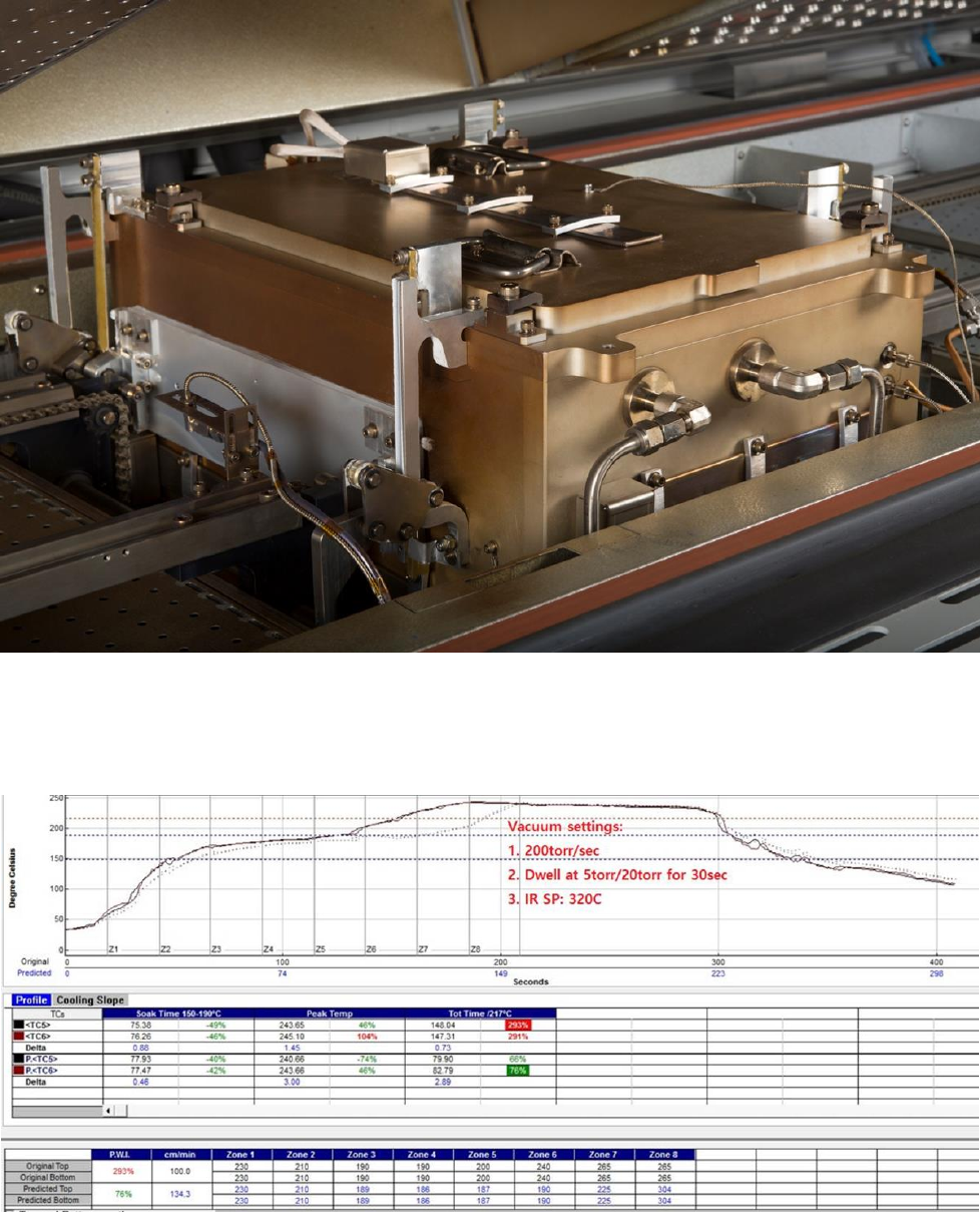
Figure 7- Vacuum Chamber Detail
Two reflow profiles were used. Both had similar 150°C to 200°C soak profiles for approximately 77 seconds, and peak
temperatures measured between 240° and 245°C. Profile 1 used a 30 second dwell time in the vacuum chamber. Profile 2
used a 60 second dwell time. These reflow profiles are shown in figures 8 and 9.
Figure 8- Reflow Profile 1; 30 seconds dwell in vacuum