Void Reduction in Bottom Terminated Components Using Vacuum Assisted Reflow - 第6页
Figure 9- Reflow Profile 2; 60 seconds dwell in vacuum In order to m aintain the reflow temperature in the vacuum cha mber, an IR heating ele ment is incorpor ated into t he upper surface of the vacuum c hamber. A set po…
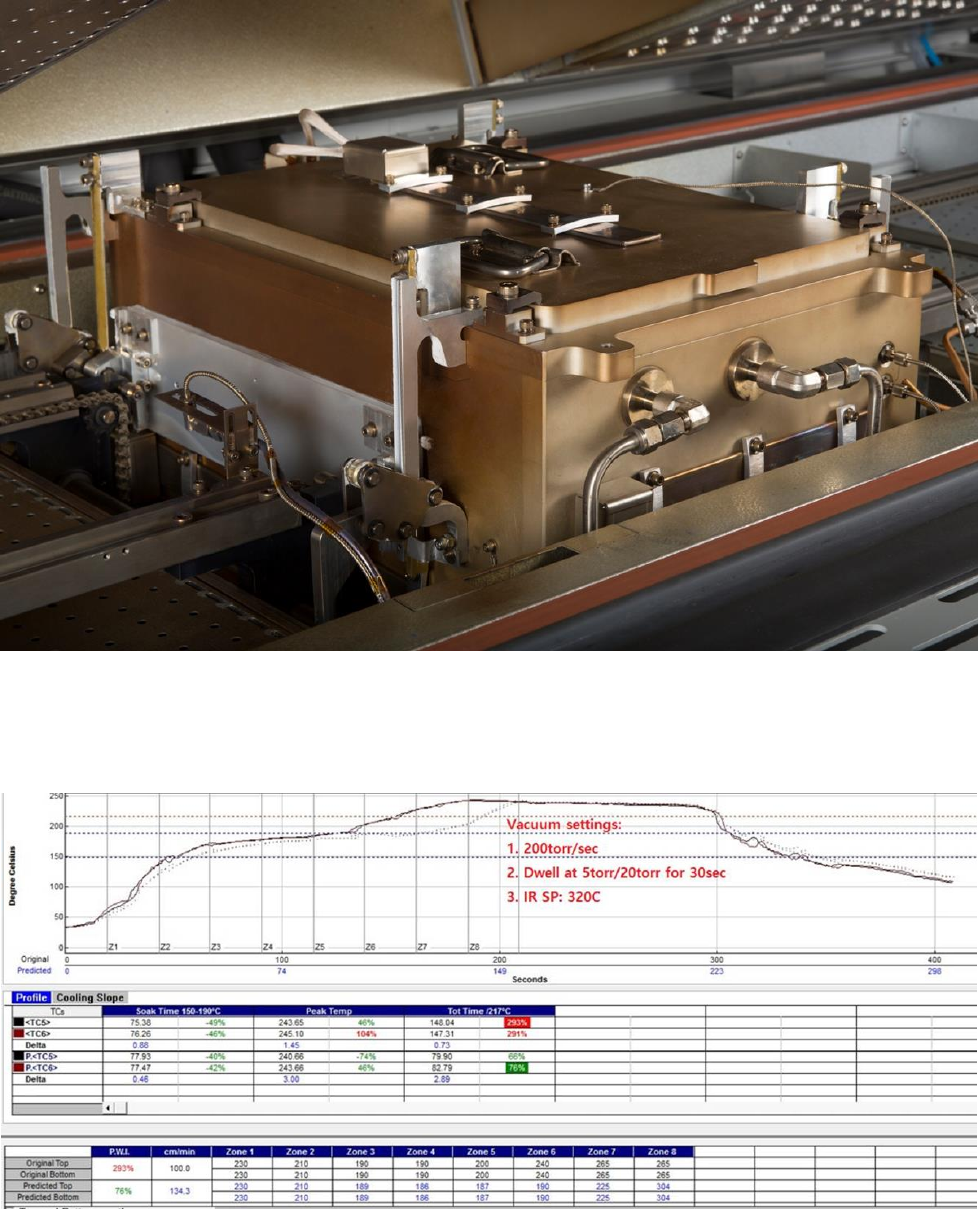
Figure 7- Vacuum Chamber Detail
Two reflow profiles were used. Both had similar 150°C to 200°C soak profiles for approximately 77 seconds, and peak
temperatures measured between 240° and 245°C. Profile 1 used a 30 second dwell time in the vacuum chamber. Profile 2
used a 60 second dwell time. These reflow profiles are shown in figures 8 and 9.
Figure 8- Reflow Profile 1; 30 seconds dwell in vacuum
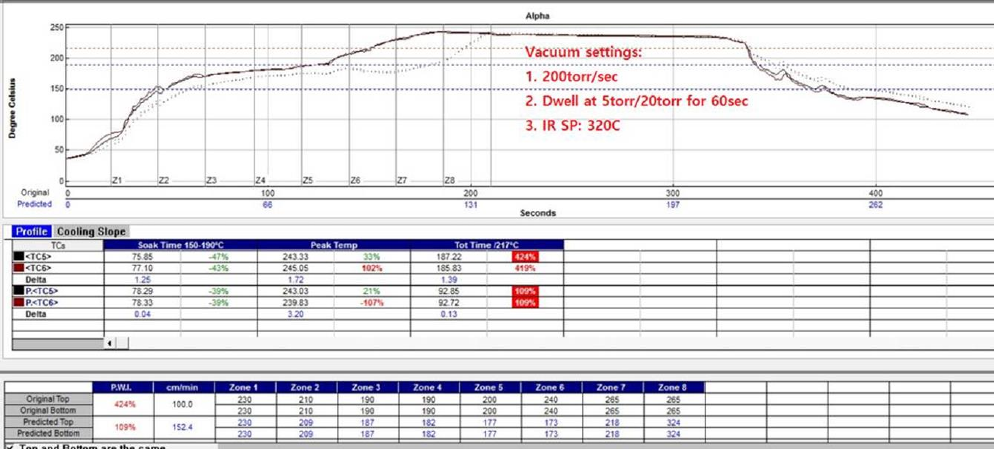
Figure 9- Reflow Profile 2; 60 seconds dwell in vacuum
In order to maintain the reflow temperature in the vacuum chamber, an IR heating element is incorporated into the upper
surface of the vacuum chamber. A set point of 320°C is needed to maintain the peak reflow temperature depicted in Figures 8
and 9.
Experimental Procedure
In addition to the 2 x 2 x 4, pressure, dwell time and surface finish elements of the experiment, several paste print patterns
were used on the MLF 100 center heat sink pad. It has been reported that by providing channels for vapor to escape, BTC
voiding can be reduced [6]. For each condition 3 sets of test vehicles and components were used. There were a total of 48
assemblies, each with 3 BTCs and one BGA, resulting in a total of 28,176 solder joints. After reflow, 2D X-ray images were
developed and representative images are shown in Appendix A.
Results and Discussion
Based on the results from this study indicated in Appendix A, void reduction under vacuum reflow has very little dependence
on surface finish. Now that this is understood, it would be interesting to see if prior lead free reflows would have an effect on
voiding, particularly with the immersion tin finish. Creation of increased Cu
6
Sn
5
intermetallic at the pad surface makes this a
potentially challenging substrate for lead free solder applications.
Also demonstrated in this study was that the level of vacuum (5 torr and 20 torr) had a marginal effect on the void reduction.
Both levels of vacuum gave extremely low (well below 0.2% in the MLF 100 heat sink area) levels of voiding as a % of the
total area of the solder joint. From this result, there appears to be no marginal return in generating a lower level of vacuum
than 20 torr. Moreover, there was a lack of response for dwell time under vacuum when the solder in the assemblies is
above the alloy liquidus (218°C). The 60 second dwell samples showed similar levels of void reduction when compared to
the 30 second dwell time samples. Both dwell times showed excellent void reduction results so there was no room for
improvement by increasing the dwell time to 60 seconds. More experiments need to be run to determine what the curves of
vacuum level and vacuum dwell time versus voiding area might look like, or whether void reduction is a simple step function
for both of these DOE parameters.
The most obvious conclusion of this work was that applying vacuum while the solder alloy is in the liquid phase has a
significant affect on reducing BTC component voiding. The BGA 256 samples had low levels of voiding with or without
vacuum. This was expected because of the long soak profile and relatively small deposits (.4mm circles, .1mm high) of the
BGA packages. The effect on the larger area solder paste deposits, the heat sinks on the MLF 100 and TO-252 packages, was
much more significant as can be seen in figures 10 and 11.
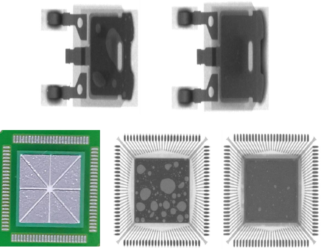
Figure 10- TO-252 Package with no vacuum (left) and 5 torr for 60 seconds vacuum (right)
Figure 11- MLF 100 Package with no vacuum (center) and 5 torr for 60 seconds vacuum (right). Note channel
pattern used (left).
Conclusions
The use of a vacuum chamber in an in-line convection reflow oven has the potential to reduce voiding significantly in large
area pads designed to draw heat away from power semiconductors. This allows for more effective heat dissipation, less heat
generation, longer battery life and more reliable assemblies.
Using 20 torr of vacuum and 30 seconds of dwell time was sufficient to cause this significant reduction in voiding. Sixty
second dwell in the vacuum showed no additional (significant) decrease in the level of voiding observed. Likewise, reducing
the atmospheric pressure from 20 torr to 5 torr did not show a measureable improvement in void reduction. Finally, the four
surface finishes used in this study all showed the same level of void reduction using the vacuum process while the solder
alloy was in the molten phase.
References
1. Herron, D, Liu, Y, and Lee, N.C., Voiding Control At QFN Assembly, SMTAI, Forth Worth, TX, 2011.
2. Nguyen J., Geiger D., Shangguan D. Assembly Challenges of Bottom Terminated Components APEX, San Diego, CA,
2012.
3. Aspandiar R., “Voids in Solder Joints”, SMTAI Conference Proceedings, 2006.
4. Holtzer M, Mok T.W., Methods of Reducing or Eliminating Voids in BGA and BTC Components, SMTA South Asia,
2016
5. IPC Solder Products Value Council, “The Effect of Voiding in Solder Interconnections Formed from Lead-free Solder
Pastes with Alloys of Tin, Silver and Copper”, White Paper, IPC.
6. Brown, S., Holtzer, M., Process Considerations in Reducing Voiding in High Reliability Lead Free Solder Joints