NPM-D3维修手册.pdf - 第122页
NPM-D3 SERVICE MANUAL 4.6 Optional Units Page 4-84 EJM6D3-MB-04SM-02.DOC Board Detection Sensor Layout 基板検出センサレイアウト 基板检测传感器的布局 No. Sensor name センサ名称 传感器名称 Connecto r No. コネクタ No. 连接器 No. Emission frequency 投光周期 照光周期 1 …
NPM-D3
SERVICE MANUAL
4.6 Optional Units
EJM6D3-MB-04SM-02.DOC Page 4-83
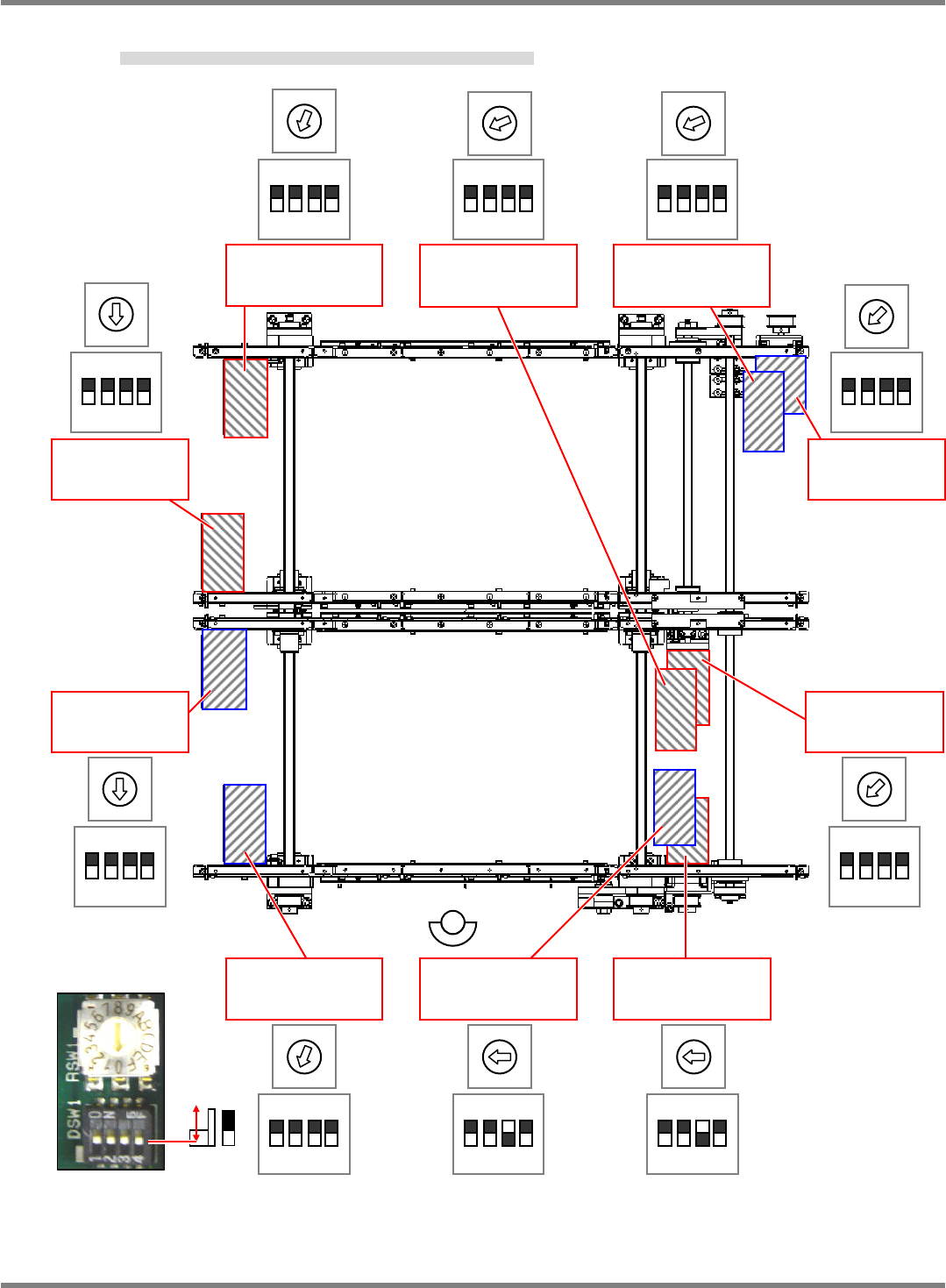
3. Set the DIP switches and rotary switch for each motor to be used. (Fig. 3)
モータの使用か所ごとに DIP スイッチとロータリースイッチの設定を行います。(Fig. 3)
在每个电机的使用位置上,进行 DIP SW 和旋转 SW 的设定。(Fig. 3)
Fig. 3: Factory-setting
4
Lane 2
Lane 1
2
1234
ON
1
0
0
1 2 3 4
ON
1 2 3 4
ON
1234
ON
1 2 3 4
ON
1234
ON
2
3
1
3
4
123 4
ON
1234
ON
1 2 3 4
ON
1 2 3 4
ON
M638 Motor
(Lane 2 width
adjustment)
M601 Motor
(Lane 1 transfer)
左待機・固定
M607 Motor
(Lane 1 width
adjustment)
M63C Motor
(Lane 2 transfer)
左待機・可動
M634 Motor
(Lane 2 transfer)
左待機・固定
M636 Motor
(Lane 2 transfer)
右待機
M603 Motor
(Lane 1 transfer)
右待機
M602 Motor
(Lane 1 transfer)
実装部
M609 Motor
(Lane 1 transfer)
左待機・可動
M635 Motor
(Lane 2 transfer)
実装部
NPM-D3
SERVICE MANUAL
4.6 Optional Units
Page 4-84 EJM6D3-MB-04SM-02.DOC
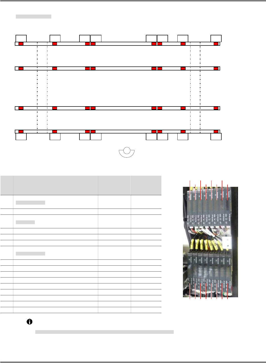
Board Detection Sensor Layout
基板検出センサレイアウト
基板检测传感器的布局
No.
Sensor name
センサ名称
传感器名称
Connector
No.
コネクタ
No.
连接器
No.
Emission
frequency
投光周期
照光周期
1
Left standby board detection 1 #1
左待機
基板検出
1 #1
左待机基板检测
1 #1
B1127 F0
2 Left standby board detection 2 #1
B1131 F0
3
Board detection 1 #1
基板検出
1 #1
基板检测
1 #1
B1136 F03
4 Board detection 2 #1 B1113 F02
5 Board detection 4 #1 B1122 F02
6 Board detection 5 #1 B1115 F03
7
Right standby board detection 1 #1
右待機
基板検出
2 #1
右待机基板检测
2 #1
B1121 F0
8 Right standby board detection 2 #1 B1120 F0
9 Left standby board detection 1 #2 B1133 F0
10 Left standby board detection 2 #2 B1132 F0
11 Board detection 1 #2 B1134 F03
12 Board detection 2 #2 B1112 F02
13 Board detection 4 #2 B1124 F02
14 Board detection 5 #2 B1117 F03
15 Right standby board detection 1 #2 B1126 F0
16 Right standby board detection 2 #2 B1130 F0
Light intensity / threshold when the rails are at origins (Rail 1: 460.5 mm / Rail 2: 216.5 mm) must
be 100 or more.
原点時のレール幅
(
レール
1 : 460.5mm /
レール
2 : 216.5mm)
における光量
/
閾値が
100
以上であること。
在原点时的轨道宽度
(
轨道
1: 460.5 mm /
轨道
2: 216.5 mm)
的光量
/
阈值应在
100
以上。
(1)
Fig. 1
(2) (3) (4) (5) (6) (7) (8)
(9) (10) (11) (12) (13) (14) (15) (16)
(1) (2) (3) (4) (5) (6) (7) (8)
(9)
(10)
(11)
(12)
(13)
(14)
(15)
(16)
Fig. 2
NPM-D3
SERVICE MANUAL
4.6 Optional Units
EJM6D3-MB-04SM-02.DOC Page 4-85
Connector Check by Transfer Specifications
搬送仕様識別コネクタ確認
搬送规格识别连接器确认
Transfer spec.
搬送仕様
搬送规格
FLOW Bit 0 Bit 1 Bit 2 Bit 3 PLACE1 PLACE2 PLACE3
B1223P B1224P B1225P B1226P B1227P
PC dual normal
flow (short)
PC
デュアル正流れ
(
ショート
)
PC
双式正流向
×
○
○
○
×
○
×
×
PC dual reverse
flow (short)
PC
デュアル逆流れ
(
ショート
)
PC
双式逆流向
○
○
○
○
×
×
×
×
PC dual normal
flow (long)
PC
デュアル正流れ
(
ロング
)
PC
双式正流向
×
×
○
○
×
○
○
×
PC dual reverse
flow (long)
PC
デュアル逆流れ
(
ロング
)
PC
双式逆流向
○
×
○
○
×
×
○
×
○
: With short connector
ショートコネクタあり
有短的连接器
×
: Without short connector
ショートコネクタなし
无短的连接器
Light intensity / threshold when the rails are at origins (Rail 1: 460.5 mm / Rail 2: 216.5 mm) must be 100
or more.
原点時のレール幅
(
レール
1 : 320.5 mm
・
593.5 mm /
レール
2 : 320.5 mm)
における光量
/
閾値が
100
以上であること。
在原点时的轨道宽度
(
轨道
1 : 460.5 mm /
轨道
2 : 216.5 mm)
的光量
/
阈值应在
100
以上。
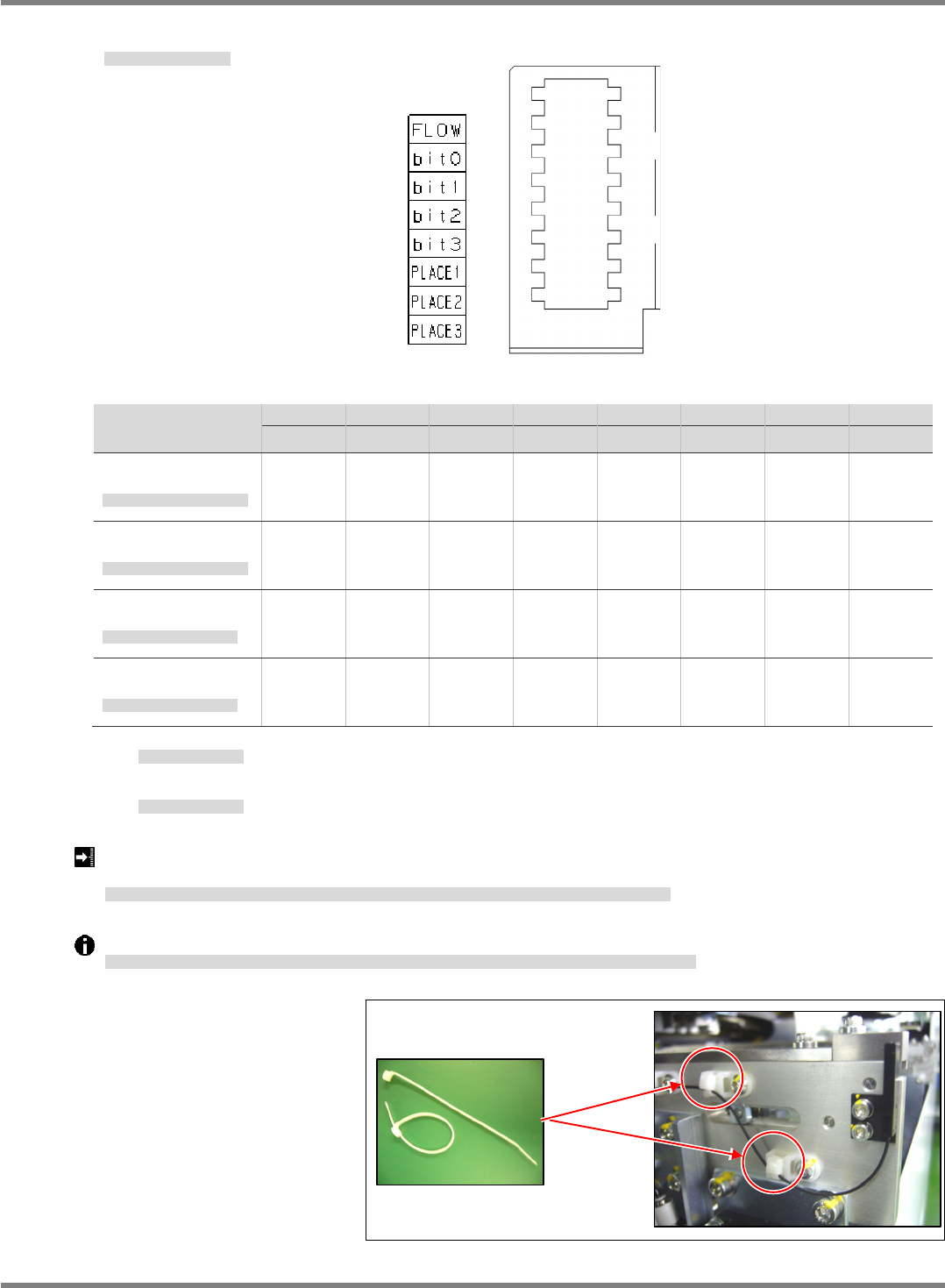
Dedicated cable ties are used to bundle fiber sensor cables so as not to damage the fibers. (Fig. 2)
ファイバーセンサケーブルの結束には、ファイバーへのダメージを防止するために、専用の結束バンドを使用します。
(Fig. 2)
捆束光纤传感器时,为了防止光纤的损伤,使用专用的捆束带。
(Fig. 2)
Fig. 2
N510039983AA
Fig. 1