NPM-D3维修手册.pdf - 第132页
NPM-D3 Service Manual 5.1 Head Unit Page 5-4 EJM6D3-MB-05SM-00( 編集中 ).DOC Head Unit Attaching ヘッドユニット取り付け 头装置的安装 Torque w rench: QL25N (TOHNICHI) トルクレンチ 扭矩扳手 Long bit: N510046662AA ロングビット 长钻头 2. 1. Hold the head unit b…
NPM-D3
Service Manual
5.1 Head Unit
EJM6D3-MB-05SM-00(
編集中
).DOC Page 5-3
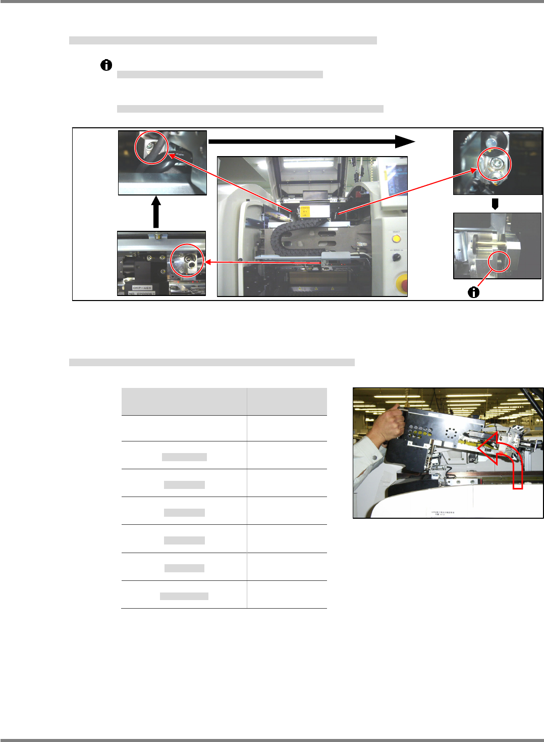
5. Loosen the head unit installation bolts (3-M6 20) in the order of (1) bottom right, (2) upper left and (3)
upper right, and remove the screw part. (Fig. 1)
ヘッドユニット取り付けボルト(3-M620)を①右下、②左上、③右上の順に緩め、ネジ部を全て抜きます。(Fig. 1)
将头装置安装螺栓(3-M620),按照①右下、②左上,③右上的顺序拧松,拔出全部螺丝部。(Fig. 1)
The top right bolt (3) cannot be fully unscrewed if the installation surface is attached firmly.
③右上のボルトは、取り付け面が密着しているとネジ部が全て抜けません。
③右上的螺栓,如果安装面很紧贴,不能将全部螺丝部拔出。
Slide the head unit to the rear side and check that the bolt is fully unscrewed.
ヘッドユニットを奥側にスライドさせ、ボルトのネジ部が完全に抜けたことを確認してください。
先将头装置滑动到内侧,确认螺栓的螺丝部全部拔掉。
6. Hold the head unit by the handle and detach the head unit to the front while lifting the handle upward.
(Fig. 3)
ヘッドユニット上部の取手を持ち、上部に持ち上げながら手前にヘッドユニットを取り外します。(Fig. 3)
握住头装置上部的把手,一边抬起,一边将头装置向前取下。(Fig. 3)
Head type
ヘッド種類
头种类
Weight
重量
重量
軽量
16
ノズルヘッド
6.5 k
g
12-nozzle head
12
ノズルヘッド
12
吸嘴吸头
7.6 k
g
8-nozzle head
8
ノズルヘッド
8
吸嘴吸头
8.3 k
g
3-nozzle head
3
ノズルヘッド
3
吸嘴吸头
8.5 k
g
2-nozzle head
2
ノズルヘッド
2
吸嘴吸头
7.2 k
g
2D Inspection Head
2D
検査ヘッド
2D
检查头
5.7 k
g
Dispensing Nozzle Head
塗布ノズルヘッド
点胶喷嘴头
7.5 k
g
Fig. 3
Fig. 1
(1) Bottom
right
(2) Upper
left
(3) Upper
right
◎
◎
◎
NPM-D3
Service Manual
5.1 Head Unit
Page 5-4 EJM6D3-MB-05SM-00(
編集中
).DOC
Head Unit Attaching
ヘッドユニット取り付け
头装置的安装
Torque wrench:
QL25N (TOHNICHI)
トルクレンチ
扭矩扳手
Long bit:
N510046662AA
ロングビット
长钻头
2.
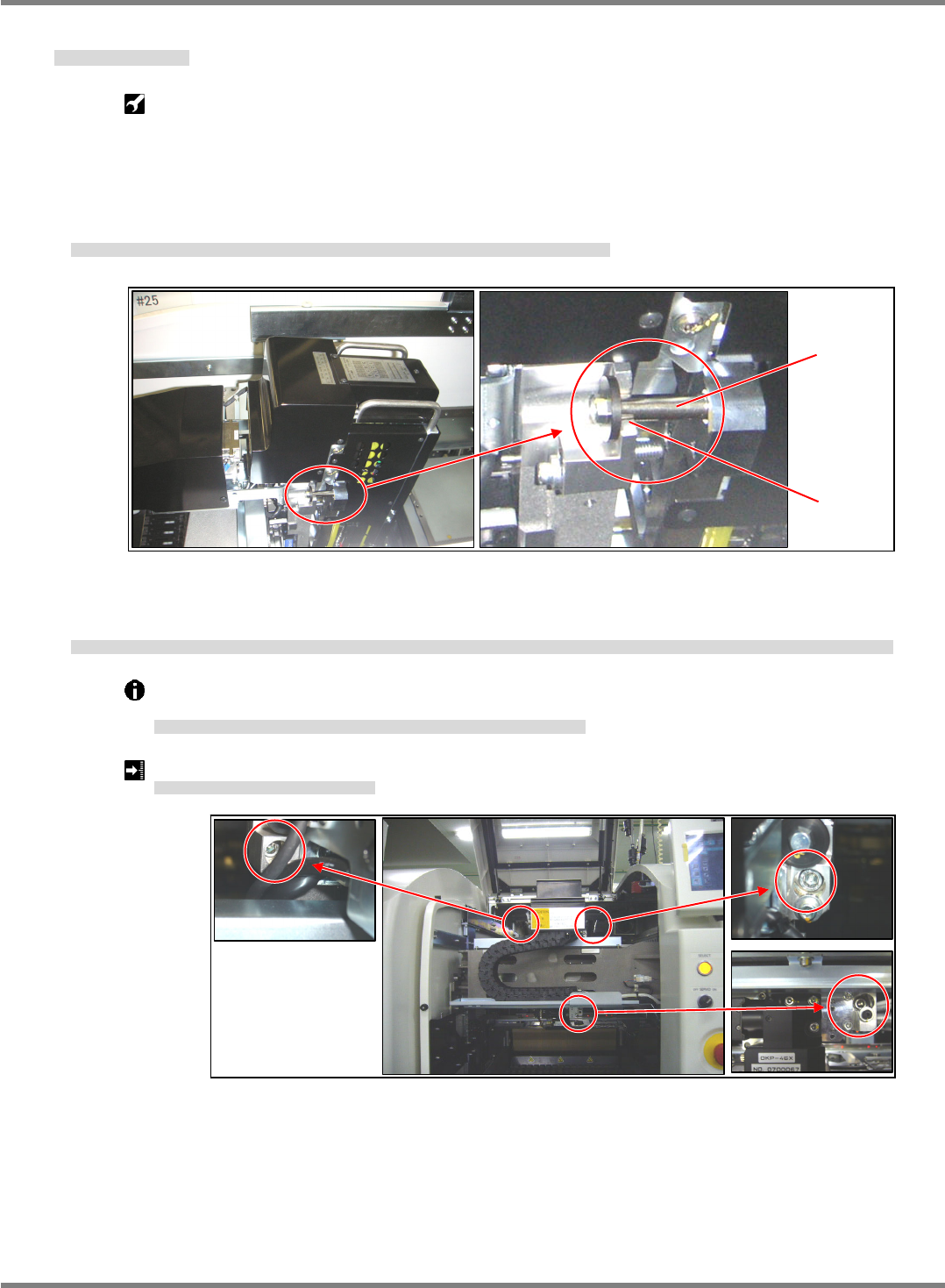
1. Hold the head unit by the handle and set the head unit spacers on the U groove of the X-axis head
installation part. (Fig. 1)
ヘッドユニット上部の取手を持ち、X 軸ヘッド取り付け部の U 溝部にヘッドユニットのスペーサを乗せる。(Fig. 1)
拿住头装置上部的把手,将头装置的垫片放在 X 轴头装置安装部的 U 沟槽部上。(Fig. 1)
2. The head unit is positioned with the positioning pins (2-5). Pull the head unit to the front, tighten the
installation bolts (3-M6 x 20), and check that the installation surfaces are flush with each other.
ヘッドユニットは規正ピン(2-φ5)で位置決めされます。ヘッドユニットを手前に引き、取り付けボルト(3-M6×20)を締め付け、取り付け面が密着していることを確認します。
头装置被调整销(2- 5)定位。将头装置拉到前面,拧紧安装螺栓(3-M6×20)后,确认安装面是否紧贴。
The installation bolts of the head unit should be tightened to the prescribed torque using a
torque wrench.
ヘッドユニットの取り付けボルトはトルクレンチを使用して規定のトルクで締め付けます。
头装置的安装螺栓,按照规定的扭矩,用扭矩扳手拧紧。
Head unit installation bolt tightening torque: 6
0.5 N
ヘッドユニット取り付けボルト締め付けトルク
头装置安装螺栓拧紧扭矩
Fig. 1
U groove
Spacer
Fig. 2
NPM-D3
Service Manual
5.1 Head Unit
EJM6D3-MB-05SM-00(
編集中
).DOC Page 5-5
3. Turn ON the power.
電源を ON します。
将电源置于 ON。
When the tray feeder is connected, connect the tray feeder before turning ON the power.
トレイフィーダが接続されている場合は、電源を
ON
する前にトレイフィーダを接続します。
已连接托盘料架时,将电源置于
ON
之前连接托盘料架。
4. Attach the feeder table cover.
フィーダテーブルカバーを取り付けます。
安装料架工作台的盖。
‘1.2.3 Feeder Table Cover Detaching and Attaching’ in the Maintenance Manual.
5. Attach the cart.
交換台車を取り付けます。
安装交换台车。
‘1.2.2 Cart Detaching and Attaching’ in the Maintenance Manual.
6. This completes the head unit attaching.
以上でヘッドユニットの取り付けは完了です。
以上头装置的安装作业完成。
Perform various teachings according to the head replacement status.
ヘッド交換状況に応じて各種のティーチングを行います。
根据头状况,进行各种示教。