NPM-D3维修手册.pdf - 第133页
NPM-D3 Service Manual 5.1 Head Unit EJM6D3-MB-05SM-00( 編集中 ).DOC Page 5-5 3. Turn ON the power. 電源を ON します。 将电源置于 ON 。 When the tray feeder is connect ed, connect the tray feeder befo re turning ON the power. トレイフィーダが接続さ…
NPM-D3
Service Manual
5.1 Head Unit
Page 5-4 EJM6D3-MB-05SM-00(
編集中
).DOC
Head Unit Attaching
ヘッドユニット取り付け
头装置的安装
Torque wrench:
QL25N (TOHNICHI)
トルクレンチ
扭矩扳手
Long bit:
N510046662AA
ロングビット
长钻头
2.
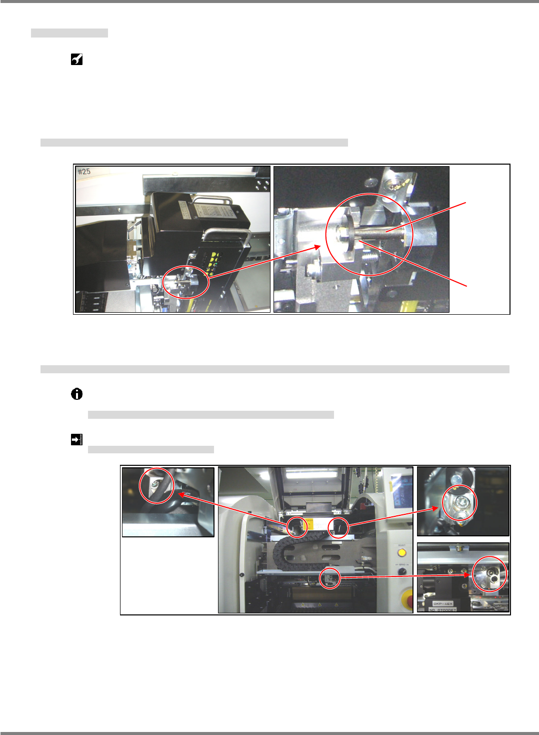
1. Hold the head unit by the handle and set the head unit spacers on the U groove of the X-axis head
installation part. (Fig. 1)
ヘッドユニット上部の取手を持ち、X 軸ヘッド取り付け部の U 溝部にヘッドユニットのスペーサを乗せる。(Fig. 1)
拿住头装置上部的把手,将头装置的垫片放在 X 轴头装置安装部的 U 沟槽部上。(Fig. 1)
2. The head unit is positioned with the positioning pins (2-5). Pull the head unit to the front, tighten the
installation bolts (3-M6 x 20), and check that the installation surfaces are flush with each other.
ヘッドユニットは規正ピン(2-φ5)で位置決めされます。ヘッドユニットを手前に引き、取り付けボルト(3-M6×20)を締め付け、取り付け面が密着していることを確認します。
头装置被调整销(2- 5)定位。将头装置拉到前面,拧紧安装螺栓(3-M6×20)后,确认安装面是否紧贴。
The installation bolts of the head unit should be tightened to the prescribed torque using a
torque wrench.
ヘッドユニットの取り付けボルトはトルクレンチを使用して規定のトルクで締め付けます。
头装置的安装螺栓,按照规定的扭矩,用扭矩扳手拧紧。
Head unit installation bolt tightening torque: 6
0.5 N
ヘッドユニット取り付けボルト締め付けトルク
头装置安装螺栓拧紧扭矩
Fig. 1
U groove
Spacer
Fig. 2

NPM-D3
Service Manual
5.1 Head Unit
EJM6D3-MB-05SM-00(
編集中
).DOC Page 5-5
3. Turn ON the power.
電源を ON します。
将电源置于 ON。
When the tray feeder is connected, connect the tray feeder before turning ON the power.
トレイフィーダが接続されている場合は、電源を
ON
する前にトレイフィーダを接続します。
已连接托盘料架时,将电源置于
ON
之前连接托盘料架。
4. Attach the feeder table cover.
フィーダテーブルカバーを取り付けます。
安装料架工作台的盖。
‘1.2.3 Feeder Table Cover Detaching and Attaching’ in the Maintenance Manual.
5. Attach the cart.
交換台車を取り付けます。
安装交换台车。
‘1.2.2 Cart Detaching and Attaching’ in the Maintenance Manual.
6. This completes the head unit attaching.
以上でヘッドユニットの取り付けは完了です。
以上头装置的安装作业完成。
Perform various teachings according to the head replacement status.
ヘッド交換状況に応じて各種のティーチングを行います。
根据头状况,进行各种示教。
NPM-D3
Service Manual
5.1 Head Unit
Page 5-6 EJM6D3-MB-05SM-00(
編集中
).DOC
Fig. 1
CCU / CCD
LED
Plate
Fig. 3
5.1.2 Head Camera Detaching and Attaching
ヘッドカメラ取り外し / 取り付け
头照相机的卸下和安装
Unit No.
N610067507AA
5.1.2 Head Camera Detaching
and Attaching
ヘッドカメラ取り外し
/
取り付け
头照相机的卸下和安装
Head Camera Detaching
取り外し
卸下
3.
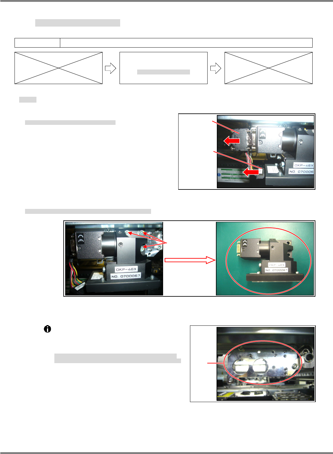
1. Disconnect the CCU/CCD and LED connectors. (Fig. 1)
CCU/CCD と LED 照明のコネクタを抜きます。(Fig. 1)
拔出 CCU/CCD 和 LED 照明的连接器。(Fig. 1)
2. Remove the bolts (3-M4 12), and the head camera can be detached.
ヘッドカメラ取り付けボルト(3-M4×12)を緩め、ヘッドカメラを外します。
拧松头照相机安装螺栓(3-M4×12),卸下头照相机。
The plate to which the head camera is
attached is positioned with the jig.
Do not loosen or remove the installation bolts
of the plate. (Fig. 3)
ヘッドカメラを取り付けるプレートは、治具にて位置決めされています。
プレートの取り付けボルトを緩めたり、外したりしないでください。(Fig. 3)
安装头装置的板被治具定位。
请不要拧松或卸下板的安装螺栓。(Fig. 3)
3-M4
×
12
Fig. 2