NPM-D3维修手册.pdf - 第135页
NPM-D3 Service Manual 5.1 Head Unit EJM6D3-MB-05SM-00( 編集中 ).DOC Page 5-7 Head Camera Attaching 取り付け 安装 Attach the head camera in the opposit e order in which it was deta ched. ヘッドカメラの取り外しと逆の手順でヘッドカメラを取り付けます。 按照头照相机的卸下…
NPM-D3
Service Manual
5.1 Head Unit
Page 5-6 EJM6D3-MB-05SM-00(
編集中
).DOC
Fig. 1
CCU / CCD
LED
Plate
Fig. 3
5.1.2 Head Camera Detaching and Attaching
ヘッドカメラ取り外し / 取り付け
头照相机的卸下和安装
Unit No.
N610067507AA
5.1.2 Head Camera Detaching
and Attaching
ヘッドカメラ取り外し
/
取り付け
头照相机的卸下和安装
Head Camera Detaching
取り外し
卸下
3.
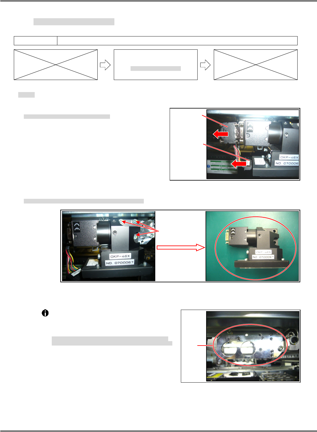
1. Disconnect the CCU/CCD and LED connectors. (Fig. 1)
CCU/CCD と LED 照明のコネクタを抜きます。(Fig. 1)
拔出 CCU/CCD 和 LED 照明的连接器。(Fig. 1)
2. Remove the bolts (3-M4 12), and the head camera can be detached.
ヘッドカメラ取り付けボルト(3-M4×12)を緩め、ヘッドカメラを外します。
拧松头照相机安装螺栓(3-M4×12),卸下头照相机。
The plate to which the head camera is
attached is positioned with the jig.
Do not loosen or remove the installation bolts
of the plate. (Fig. 3)
ヘッドカメラを取り付けるプレートは、治具にて位置決めされています。
プレートの取り付けボルトを緩めたり、外したりしないでください。(Fig. 3)
安装头装置的板被治具定位。
请不要拧松或卸下板的安装螺栓。(Fig. 3)
3-M4
×
12
Fig. 2

NPM-D3
Service Manual
5.1 Head Unit
EJM6D3-MB-05SM-00(
編集中
).DOC Page 5-7
Head Camera Attaching
取り付け
安装
Attach the head camera in the opposite order in which it was detached.
ヘッドカメラの取り外しと逆の手順でヘッドカメラを取り付けます。
按照头照相机的卸下相反的步骤,安装头照相机。
4.
1. Position the head camera with the positioning pin (2-
3) and secure it to the plate with the installation bolts
(3-M4 12).
ヘッドカメラを規正ピン(2-
3)で位置決めし、取り付けボルト(3-M412)でプレートに取り付けます。
用调整销(2-
3)定位头照相机,并用安装螺栓(3-M412)安装到板上。
2. Insert the CCU/CCD and LED connectors.
CCU/CCD と LED 照明のコネクタを挿入します。
插入 CCU/CCD 和 LED 照明的连接器。
NPM-D3
Service Manual
5.1 Head Unit
Page 5-8 EJM6D3-MB-05SM-00(
編集中
).DOC
5.1.3 Drawer Connector Handling
ドロアコネクタの取り扱い
抽屉式连接器的使用方法
Unit No.
N610067507AA
5.1.3 Drawer Connector
Handling
ドロアコネクタの取り扱い
抽屉式连接器的使用方法
To ensure smooth connection when the head is mounted, the drawer connectors of the
X-axis and mounting head are positioned on the respective sides with purpose-specific
jigs.
X
軸と装着ヘッドのドロアコネクタ部は、ヘッド搭載時にスムーズに接続できるように、
X
軸側とヘッド側をそれぞれに治具を使用して位置決め
されています。
X
轴和贴装头上的抽屉式连接器部,为了在搭载头时能够顺畅地连接,在
X
轴侧和头侧,都被治具定位。
X-axis Drawer Connector
X 軸ドロアコネクタ
X 轴抽屉式连接器
X-axis drawer connector positioning jig:
N610068048AA
X
軸ドロアコネクタ位置調整治具
X
轴抽屉式连接器位置调整治具
5.
1. Detach the mounting head.
装着ヘッドを取り外します。
卸下贴装头。
‘5.1.1 Head Unit Detaching and Attaching’.
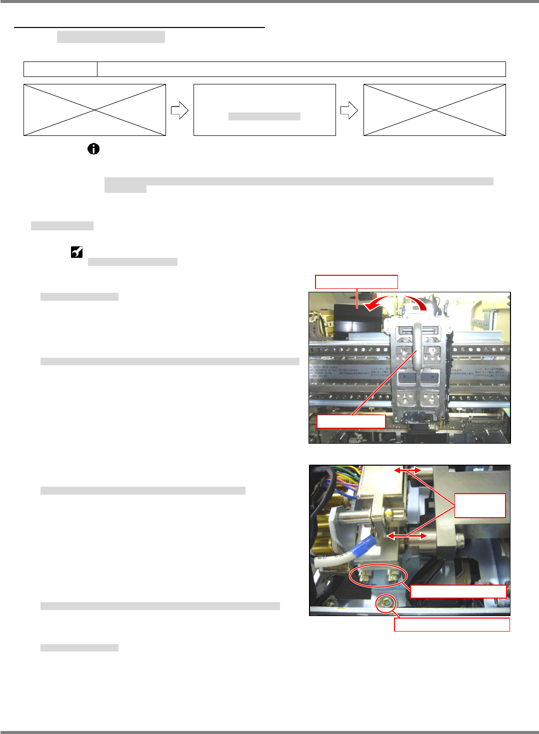
2. Detach the upper cover of the connector and attach the
X-axis drawer connector positioning jig. (Fig. 1)
接続コネクタ部の上部カバーを外し、X軸ドロアコネクタ位置調整治具を取り付けます。(Fig. 1)
拆下连接器部的上部盖后,安装 X 轴抽屉式连接器位置调整治具。(Fig. 1)
3. Adjust the position so that the pins of the jig fit in the holes
of the air coupler. (Fig. 2)
治具のピンとエアーカプラの穴が一致するように位置を調整します。(Fig. 2)
为了使治具的销和空气耦合器的孔一致,调整位置。(Fig. 2)
4. Detach the X-axis drawer connector positioning jig and
attach the upper cover of the connector.
X 軸ドロアコネクタ位置調整治具を取り外し、接続コネクタ部の上部カバーを付けます。
卸下 X 轴抽屉式连接器位置调整治具后,安装连接器的上部盖。
5. Attach the mounting head.
装着ヘッドを取り付けます。
安装贴装头。
‘5.1.1 Head Unit Detaching and Attaching’.
Fig. 1
Attach the jig.
Detach the cover.
Fig. 2
Adjust sideways position.
Adjust the height/tilt.
Adjust the
positions.