NPM-D3维修手册.pdf - 第139页
NPM-D3 Service Manual 5.2 12-nozzle Head EJM6D3-MB-05SM-00( 編集中 ).DOC Page 5-11 4. Disconnect wires (flow sen sor and cooli ng fan) from the head unit side. (Fi g. 3) ヘッドユニット側面の流量センサと冷却ファンのコネクタを抜きます。 (Fig. 3) 拔出头装置侧面的流量传…
NPM-D3
Service Manual
5.2 12-nozzle Head
Page 5-10 EJM6D3-MB-05SM-00(
編集中
).DOC
Fig. 1
Top cove
r
Side cove
r
Front cove
r
Fig. 2
Moto
r
connecto
r
Encode
r
connecto
r
CN19 CN21 CN23 CN18 CN16 CN14
CN20 CN22 CN24 CN17 CN16 CN13
CN8 CN10 CN12 CN5 CN3 CN1
CN7 CN9 CN11 CN6 CN4 CN2
5.2 12-nozzle Head
12 ノズルヘッド
12 吸嘴头
5.2.1 Z-axis Motor Replacement
Z 軸モータ交換
Z 轴电机的交换
Unit No.
N610067507AA
5.1.1 Head Unit Detaching and
Attaching
ヘッドユニット取り外し
/
取り付け
头装置的拆卸和安装
5.2.1 Z-axis Motor Replacement
Z
軸モータ交換
Z
轴电机的交换
5.1.1 Head Unit Detaching and
Attaching
ヘッドユニット取り外し
/
取り付け
头装置的拆卸和安装
7.
1. Detach the head unit.
ヘッドユニットを取り外します。
卸下头装置。
‘5.1.1 Head Unit Detaching and Attaching’
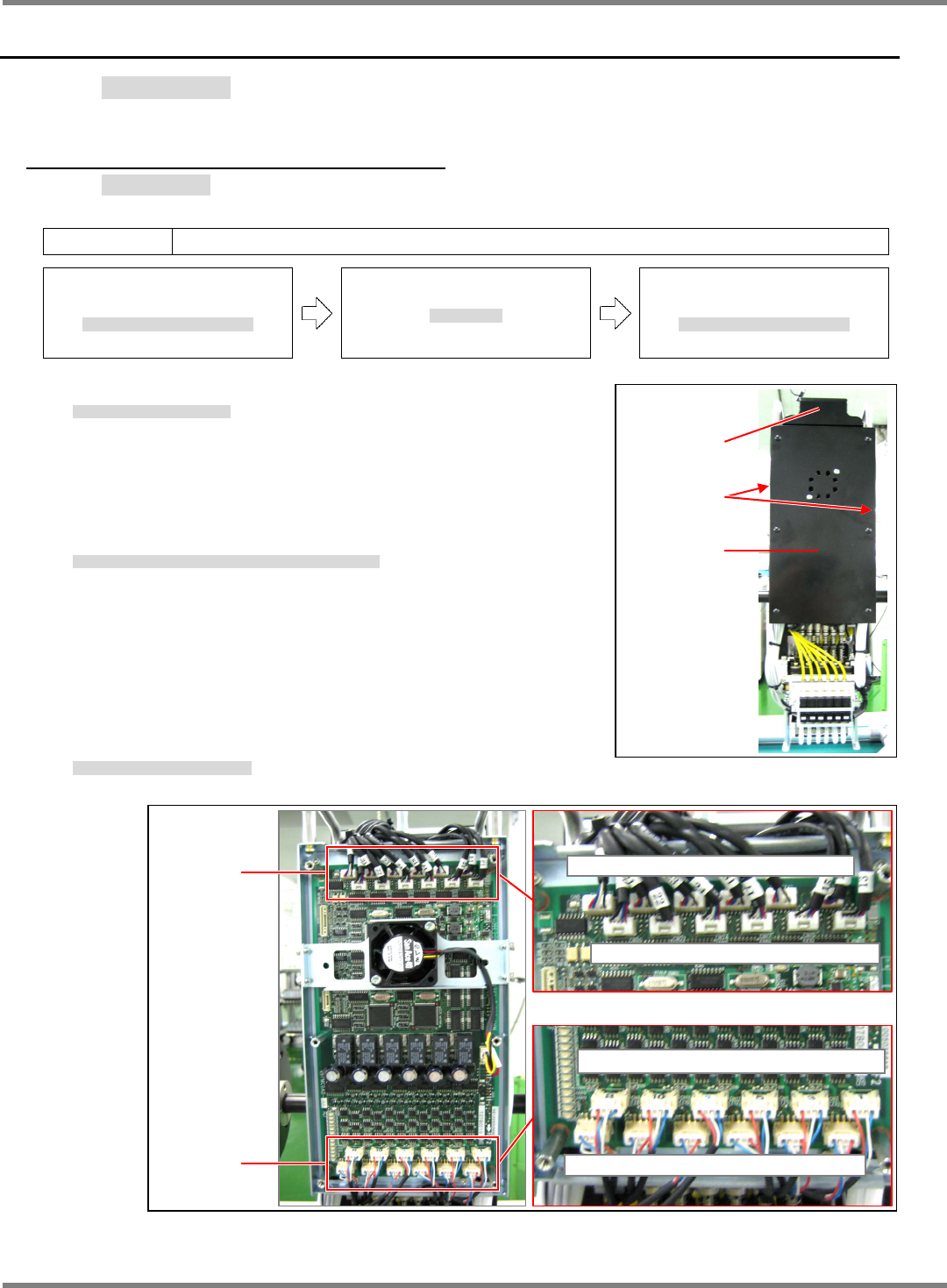
2. Detach the covers from the top, sides and front of the head unit.
(Fig. 1)
ヘッドユニットの上面、側面、正面のカバーを外します。(Fig. 1)
拆下头装置上面、侧面、以及正面的盖。(Fig. 1)
3. Disconnect wiring from the Z-axis motor (Fig. 2)
Z 軸モータの配線を外します。(Fig. 2)
拆卸 Z 轴电机的配线。(Fig. 2)
NPM-D3
Service Manual
5.2 12-nozzle Head
EJM6D3-MB-05SM-00(
編集中
).DOC Page 5-11
4. Disconnect wires (flow sensor and cooling fan) from the head unit side. (Fig. 3)
ヘッドユニット側面の流量センサと冷却ファンのコネクタを抜きます。(Fig. 3)
拔出头装置侧面的流量传感器和冷却扇的连接器。(Fig. 3)
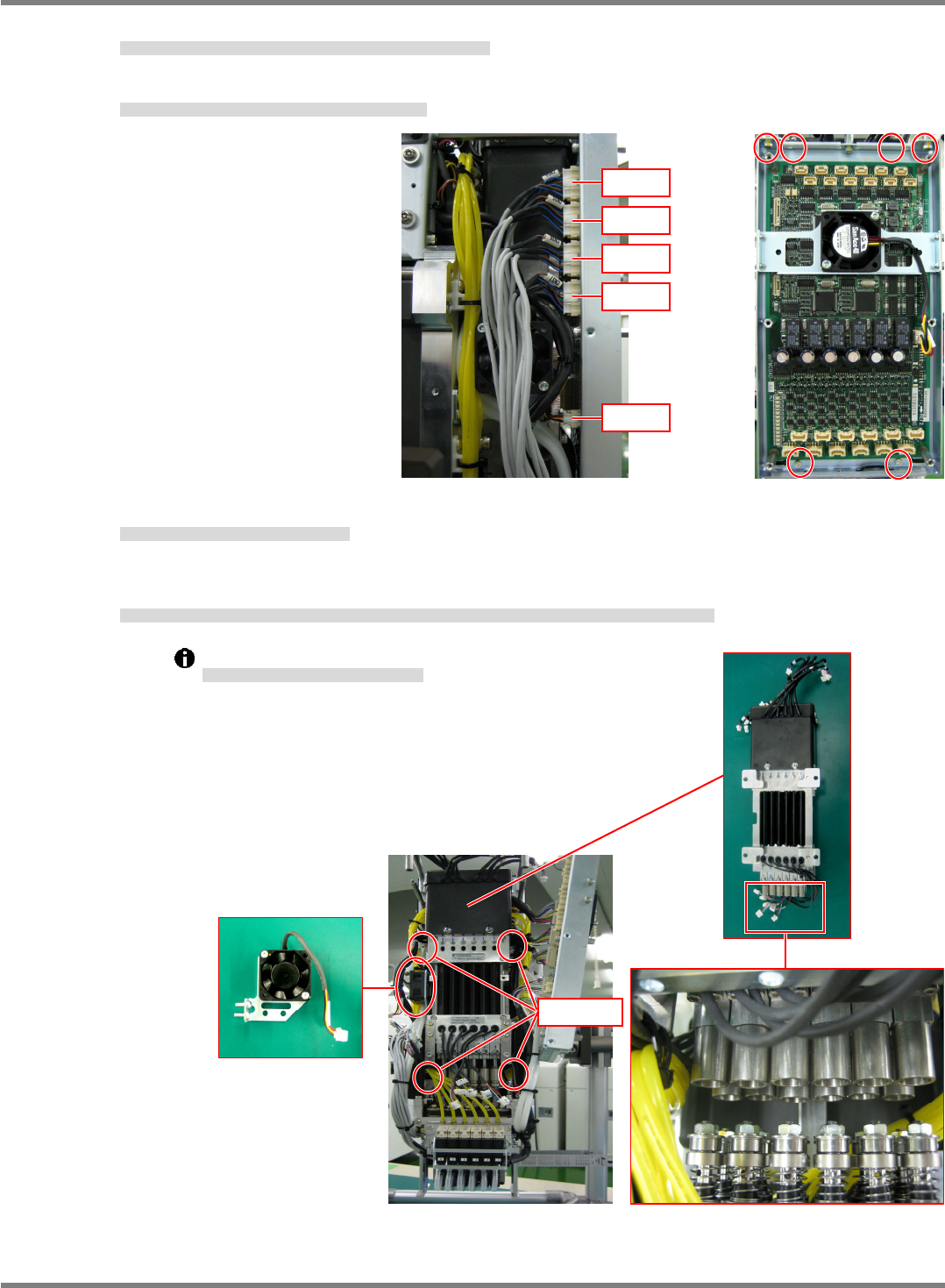
5. Remove the board installation bolts (4-M3 x 8L / 2-M4 x 8L). (Fig. 4)
基板の取り付けボルト(4-M3×8)と(2-M4×8)を外します。(Fig. 4)
卸下基板安装螺栓 (4-M3×8) 和 (2-M4×8)。(Fig. 4)
6. Detach the cooling fan. (2-M4 x 10L button bolts).
冷却ファンを外します。(ボタンボルト 2-M410)
卸下冷却扇。(圆头螺栓 2-M410)
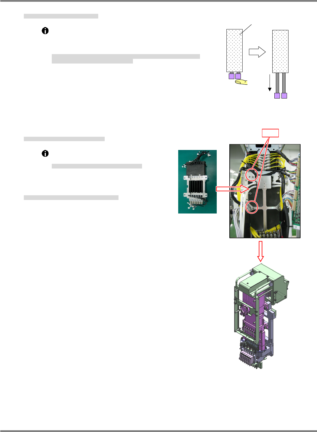
7. Remove the installation bolts (4-M5 x 20L) of the Z-axis linear motor. The shaft of the linear motor and the
spline shaft separate.
Z 軸リニアモータの、取り付けボルト(4-M520)を外し、リニアモータ部のシャフトと、スプラインシャフトを分離させます。
卸下 Z 轴线性电机的安装螺栓 (4-M520),将线性电机部的轴和花键轴分开。
Be careful not to bend the shafts.
シャフトを曲げないように注意してください。
请注意勿让轴发生弯曲。
Fig. 4
Fig. 3
CN34
CN35
CN36
CN37
CN28
Cooling fan
4-M5
20
NPM-D3
Service Manual
5.2 12-nozzle Head
Page 5-12 EJM6D3-MB-05SM-00(
編集中
).DOC
Linear moto
r
Moves to the mechanical
stopper.
Make sure the shafts fall
with their own weight.
2-
5
8. Check the sliding of the Z-axis linear motor that will be installed.
交換用 Z 軸リニアモータの摺動を確認します。
确认交换用的 Z 轴线性电机的往返移动。
Hold the linear motor with the shaft facing downwards and
the shaft tucked into the IN side of the mechanical
stopper. Then, release the shaft and confirm that it moves
to the OUT side of the mechanical stroke.
リニアモータの軸を、下方に向け、軸を入側のメカストッパーで保持した状態から開放して、
出側のメカストッパーまで動くことを確認します。
将线性电机的轴向下面,并在轴保持于入口侧的机械止动器位置的状态下开放,确认轴是否会移
动到出口侧的机械止动器位置。
9. Attach the Z-axis linear motor to the Z-axis plate.
Z 軸リニアモータを Z 軸プレートに取り付けます。
将 Z 轴线性电机安装到 Z 轴板上。
The Z axis linear motor is positioned with the
positioning pin (2-
5).
Z軸リニアモータは規正ピン
(2-
5)
で位置決めされます。
Z
轴线性电机被调整销
(2-
5)
定位。
10. Assemble the Z-axis linear motor in the order opposite to
that in which it was detached.
Z 軸リニアモータの、取り外しと逆の手順で組み立てます。
按照 Z 轴线性电机的拆卸相反步骤组装。