NPM-D3维修手册.pdf - 第144页
NPM-D3 Service Manual 5.2 12-nozzle Head Page 5-16 EJM6D3-MB-05SM-00( 編集中 ).DOC 7. Assemble related parts. 周辺部を組み立てます。 组装周边部。 8. Check the sliding resi stance of the nozzle holder. Remove then reattach the springs of the…
NPM-D3
Service Manual
5.2 12-nozzle Head
EJM6D3-MB-05SM-00(
編集中
).DOC Page 5-15
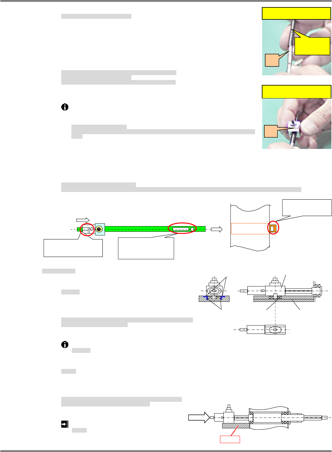
A) Insert the spline housing over the splined shaft.
スプライン軸にハウジングを挿入します。
在花键轴里插入花键壳。
=NOTE=
Use the insertion jig so as not to damage the Y packing of the spline
housing.
Thinly coat the insertion jig with grease.
This grease serves for extracting the insertion jig in later processes.
(Grease: BARRIERTA IEL / V)
ハウジングの
Y
パッキンが破損しないように挿入治具を使用します。
挿入治具にごく薄くグリスを塗布します。
後工程で挿入治具を抜く際の潤滑用。
(
グリス
=BARRIERTA
IEL / V)
为了避免壳的
Y
衬垫破损,使用插入治具。
在插入治具上薄薄地涂敷润滑脂。
在后工序中,拔出插入治具时使用的润滑脂。
(
润滑脂
=BARRIERTA
IEL / V)
Pull out the insertion jig.
Pull the insertion jig out from A to B, being careful not to detach the
B packing or bend the ball spline shaft.
挿入治具を引き抜いて外します。
A
から
B
、
B
のパッキンが外れないように、またボールスプラインを曲げないように注意して、治具を引き抜き
ます。
拔出,取下插入治具。
为了避免从
A
上脱落
B
、从
B
上脱落衬垫,另外,为了不要使花键折曲,请注意拔出治具。
B) Assemble and insert the shaft.
Insert the shaft with the numbers of the shaft and ball spline tube to the same side and the joint of
the holder connected to the shaft to the outside.
シャフト部の組立て / シャフト挿入します。
シャフトの番号とボールスプライン筒側の番号を同じ側にし、シャフトに接続済みのホルダーについているジョイントを外側に向け挿入します。
组装轴部 / 插入轴。
将轴的编号和滚珠花键筒侧的编号向同一个方向,将安装在已连接到轴上的支架上的接头向外侧插入。
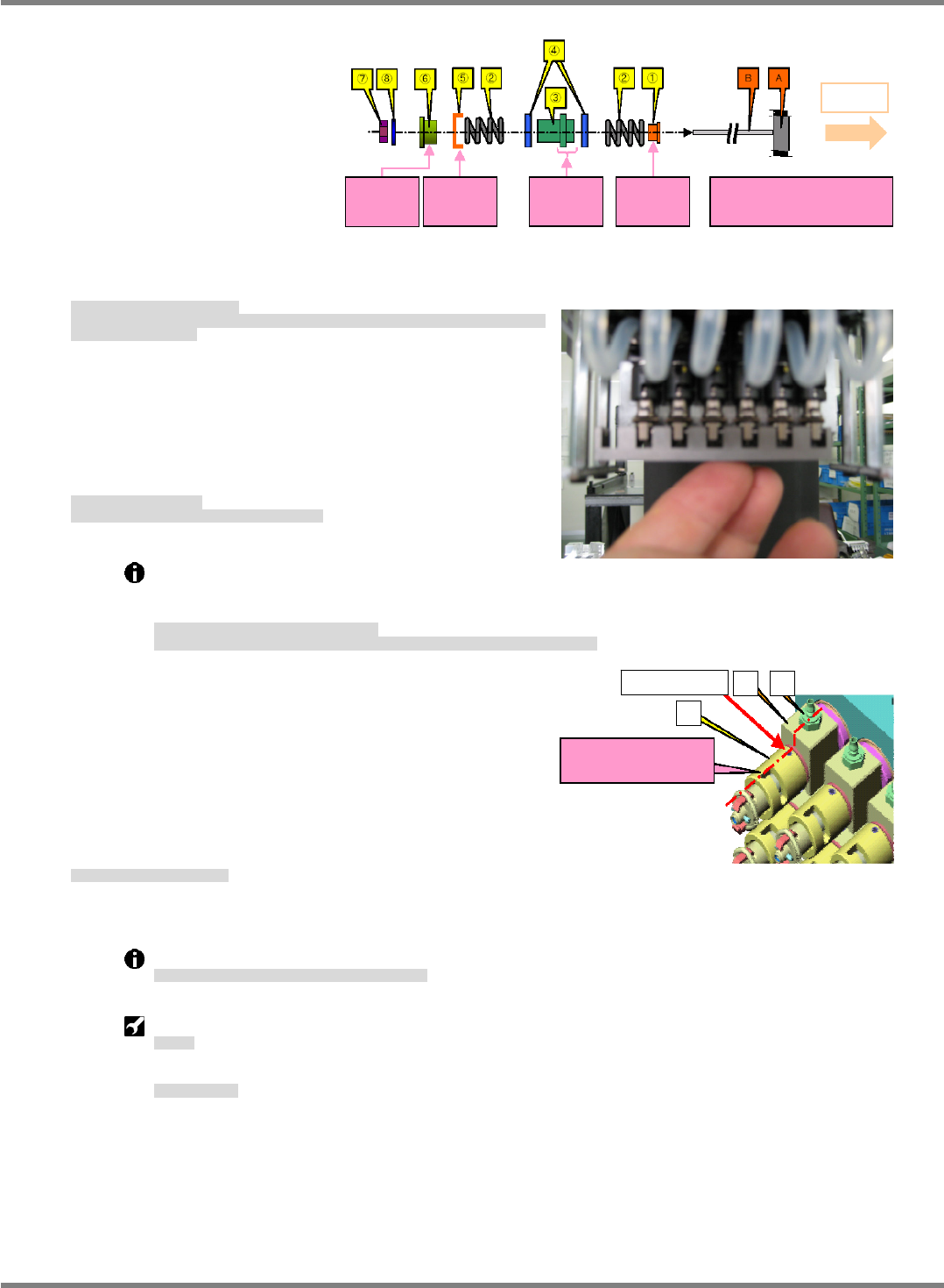
6. Nozzle shaft rotation stopper
ノズル軸回り止め部
吸嘴轴旋转停止部
A) Grease
グリス塗布
涂敷润滑脂
Check that the sliding and roller surfaces of the
plate, housing and bearing are greased.
プレートに対してハウジングとの摺動面およびベアリングとの転がり面に、グリ
スが塗布されていることを確認します。
对于板进行确认,与盒之间的往返移动面以及轴承之间的滚动面上,润滑脂是否已
被涂敷。
Grease: Panasonic LCG100
使用グリス
使用润滑脂
B) Check sliding.
摺動確認
确认往返移动值
After assembling the plate, check the sliding resistance (maximum) in a horizontal posture.
Position the shaft on the plate for measurement.
プレートを組付けた後、水平状態で摺動抵抗値
(
最大値
)
を確認します。
測定は、測定軸をプレート上方に配置して行います。
组装板后,在水平状态下确认往返移动的抵抗值
(
最大值
)
。
将测定轴配置于板的上方,进行测量。
Sliding resistance:
0.5 N
摺動抵抗
往返移动的抵抗值
Insertion jig
(Temporary)
I. Insert the jig into A.
A
II. B is fit into A + jig.
B
Lock the screw lightly while pushing the
shaft against the housing.
Center line of the
lock screw and hole
No. must be ali
g
ned.
Lock the screw on the
L-shaped side lightly.
Ball spline tube
side No.
Sliding
surface
Roller
surface
Housing
Plate
Bearing
F
Plate
NPM-D3
Service Manual
5.2 12-nozzle Head
Page 5-16 EJM6D3-MB-05SM-00(
編集中
).DOC
7. Assemble related parts.
周辺部を組み立てます。
组装周边部。
8. Check the sliding resistance of the nozzle holder.
Remove then reattach the springs of the nozzle holder and push the holder upwards. Then, release the
holder and confirm that it moves under gravity to the bottom dead center.
ノズルホルダの摺動確認をします。
ノズルホルダのバネを外してセットし、上に持ち上げた状態から放したときに、自重で下死点まで移
動することを確認します。
确认吸嘴支架的往返移动。
取下吸嘴支架的弹簧,在将其安装后,从往上面顶起的状态下让其自动落下时,确认吸嘴支架是否因自
己重量移动到下死点。
9. Adjust the nozzle
position.
Adjust the nozzle in the
direction using the
positioning jig,
and lock there.
ノズル
位置調整をします。
ノズル
位置調整治具で
方向を調整して組付けます。
调整吸嘴
位置。
用吸嘴
位置调整治具,调整
方向,并组装。
Lock C to the spline shaft by screw tight enough that it does not move.
Press C against the spline shaft so that there is no gapping from A, align parts as shown at
right and lock in place by screws (2-M2.5).
スプラインシャフトに
‘C’
を
SCREW
で仮固定
‘C’
を押し付けて、固定向きを左図のように合わせ、
C
を
SCREW (2-M2.5)
にて固定します。
在花键轴上,将
C
用
SCREW
暂时固定住。
将
C
向
A
推进,按照左图调整固定方向,将
C
用
(2
个
) SCREW
固定住。
10. Attach the head unit.
ヘッドユニットを取り付けます。
安装头装置。
‘5.1.1 Head Unit Detaching and Attaching’.
After attaching the head unit, perform the following procedures.
ヘッドユニット取り付け後は、以下の作業を実施します。
安装好头装置以后,进行以下作业。
Z plane calibration
面補正
Z
面补正
Z
Jig station
ジグステーション
治具站
Screw (M2.5)
A
B
C
A
: Housing
B: Joint
C: Holder
Installation guide
(Lengthwise groove)
A side
Convex
facing A
side
Concave
facing A
side
Short part
facing A
side
Convex
against A
side
(1) (3) (5) (6): Be careful of
orientation.
NPM-D3
Service Manual
5.2 12-nozzle Head
EJM6D3-MB-05SM-00(
編集中
).DOC Page 5-17
Fig. 1
Top cove
r
Side cove
r
Front cove
r
5.2.3
Motor Belt Replacement
モータ・ベルト交換
电机和皮带的交换
Unit No.
N610067507AA
5.1.1 Head Unit Detaching and
Attaching
ヘッドユニット取り外し
/
取り付け
头装置的拆卸和安装
5.2.3
Motor Belt Replacement
モータ・ベルト交換
电机和皮带的交换
Motor Belt Replacement
モータ・ベルト交換
电机和皮带的交换
9.
Push-pull gauge
プッシュプルゲージ
推拉规
Sonic tension-meter:
N510008902AA
超音波張力計
超声波张力计
1. Detach the head unit.
ヘッドユニットを取り外します。
卸下头装置。
== ‘5.1.1 Head Unit Detaching and Attaching’
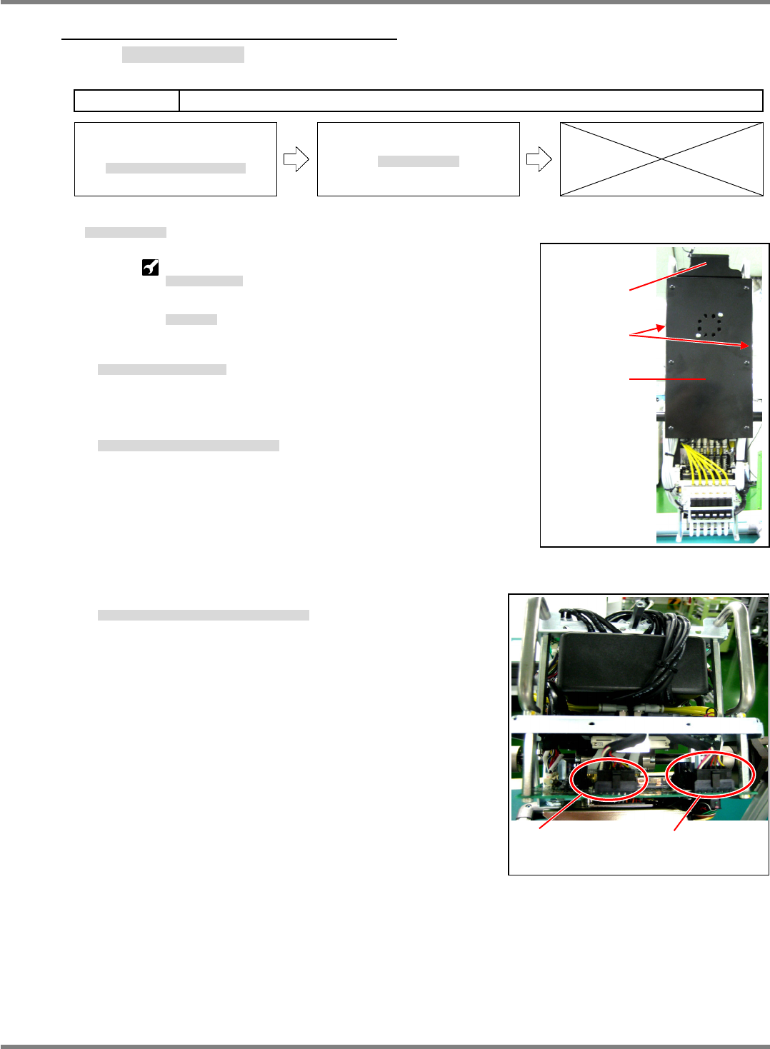
2. Detach the head unit cover. (Fig. 1)
ヘッドユニットカバーを取り外します。(Fig. 1)
拆下头装置的盖。(Fig. 1)
3. Disconnect the motor wires from the head unit. (Fig. 2)
ヘッドユニットのモータ配線を取り外します。(Fig. 2)
取下头装置的电机配线。(Fig. 2)
CN1
motor (Connector)
Pos1 to Pos6
CN3
motor (Connector)
Pos7 to Pos12
Fig. 2