NPM-D3维修手册.pdf - 第162页
NPM-D3 Service Manual 5.4 2-nozzle Head Page 5-34 EJM6D3-MB-05SM-00( 編集中 ).DOC 5.4 2-nozzle Head 2 ノズルヘッド 2 吸嘴头 5.4.1 Head Unit Replacement (Entire Unit) ヘッドユニット交換 ( 部一式 ) 头装置的交换 ( 部一套 ) Unit No. N610069507AA 5.1.1…
NPM-D3
Service Manual
5.3 8-nozzle Head
EJM6D3-MB-05SM-00(
編集中
).DOC Page 5-33
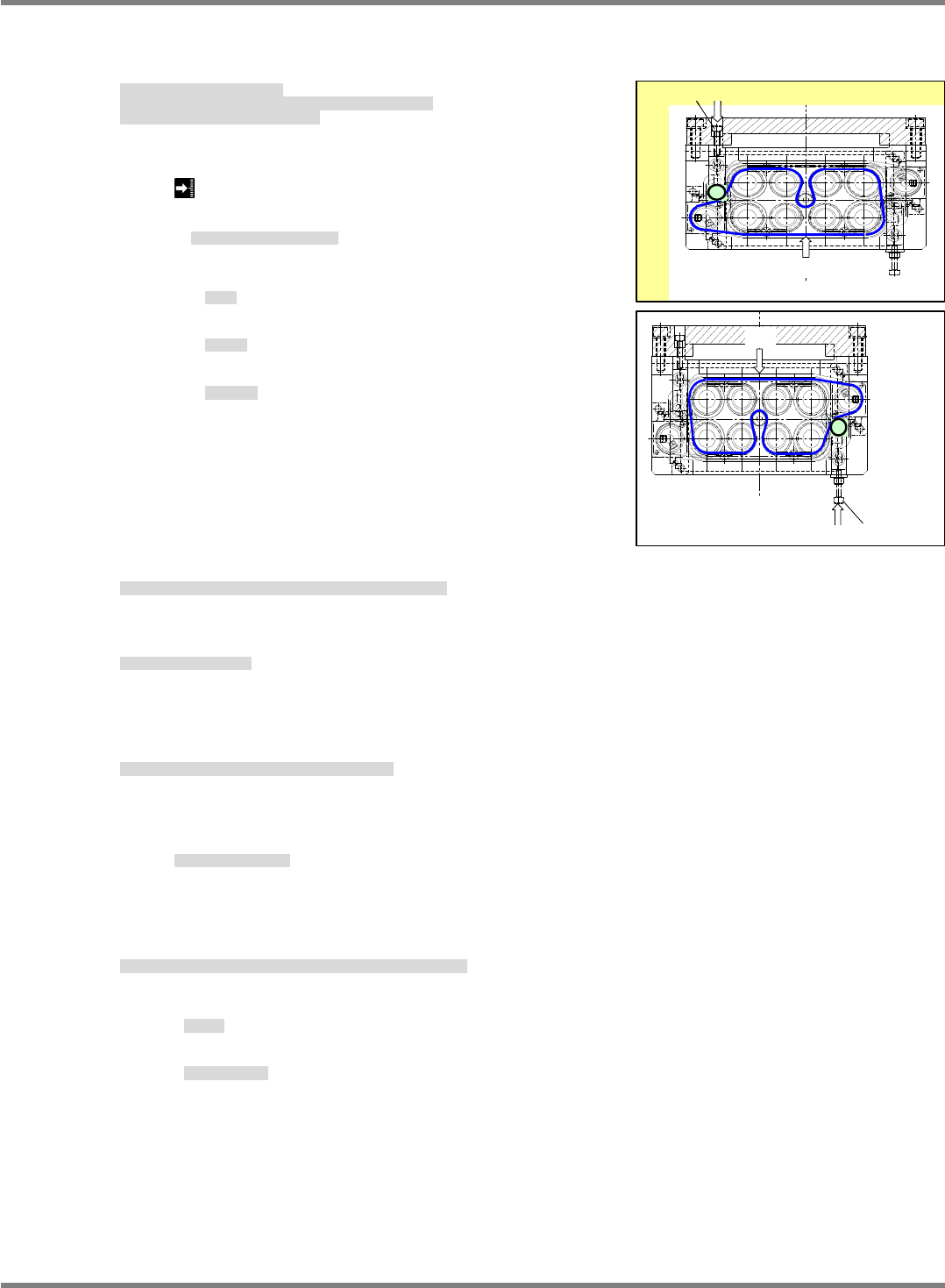
8. Adjust
belt tension.
Pull the T-belt at A and measure tension with an acoustic tension meter.
Measure tension with an acoustic tension meter.
ベルトテンション調整をします。
T-BELT の A 部を弾き、超音波張力計でテンションを測定します。
超音波張力計でテンションを測定します。
调整
皮带张力。
弹 T-BELT 的 A 部,用声波张力计测量张力。
用声波张力计测量张力。
16
2 N
Tension meter setting: Same for A and B
張力計設定
: A / B
部ともに同じ
张力计的设定
: A / B
部都一样
Span: 63 mm
スパン
跨距
Belt width: 6 mm
ベルト幅
皮带宽度
Belt mass: 1.3
g
/m
ベルト質量
皮带质量
9. Attach the
unit, sensors and valves to the head unit.
ヘッドユニッドに
ユニット / センサ / バルブ関係を取り付けます。
在头装置上安装
装置 / 传感器 / 阀关系。
10. Adjust nozzle
position.
ノズル
位置を調整します。
调整吸嘴
位置。
‘5.3.2 Ball Spline Replacement’
11. Detach the coupling between the ball spline and Z-axis ball screw.
ボールスプラインのボールネジの連結部を取り外します。
卸下滚珠花键的滚珠丝杠的连接部。
‘5.3.2 Ball Spline Replacement’.
For attaching the head unit
ヘッドユニットの取付け
头装置的安装
‘5.1.1 Head Unit Detaching and Attaching’.
12. After attaching the head unit, perform the following procedures Calibration.
ヘッドユニット取り付け後は、以下のキャリブレーションを実施します。
安装好头装置以后,进行以下作业。
• Z plane calibration
面補正
Z
面补正
Z
• Jig station
ジグステーション
治具站
下段ベルト
A部
テンション調整用ボルト
下段ベルト
A部
テンション調整用ボルト
Lower stage belt
Tension adjustment bolt
A
上段ベルト
B部
テンション調整用ボルト
上段ベルト
B部
テンション調整用ボルト
Tension adjustment bolt
Upper stage belt
B
NPM-D3
Service Manual
5.4 2-nozzle Head
Page 5-34 EJM6D3-MB-05SM-00(
編集中
).DOC
5.4 2-nozzle Head
2 ノズルヘッド
2 吸嘴头
5.4.1 Head Unit Replacement (Entire
Unit)
ヘッドユニット交換 (
部一式)
头装置的交换 (
部一套)
Unit No.
N610069507AA
5.1.1 Head Unit Detaching and
Attaching
ヘッドユニット取り外し
/
取り付け
头装置的拆卸和安装
5.4.1 Head Unit Replacement
(Entire
Unit)
ヘッドユニット交換
(
部一式
)
头装置的交换
(
部一套
)
Head Unit Detaching
取り外し
取下
Nozzle 130S / 120S
ノズル
吸嘴
A set of jig station
ジグステーション一式
治具站一套
13.
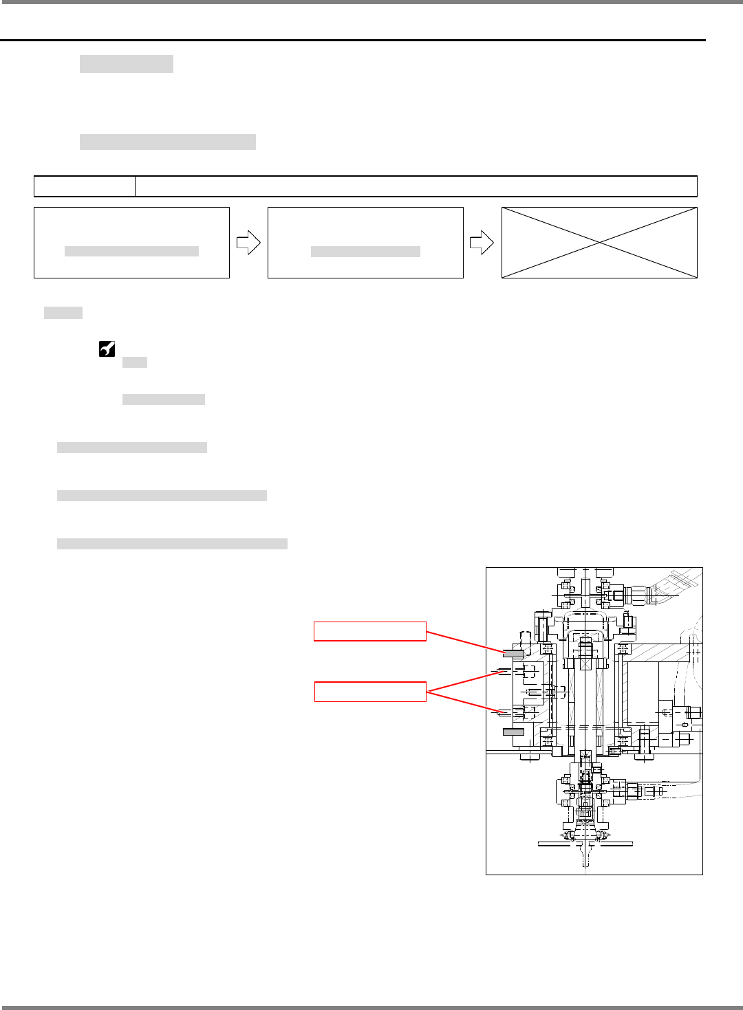
1. Disconnect connectors from the head unit. (Fig. 1)
ユニットのコネクタを外します。(Fig. 1)
卸下装置的连接器。(Fig. 1)
2. Disconnect air and vacuum tubes. (Fig. 1)
エアー用チューブ / 真空用チューブを外します。(Fig. 1)
卸下空气用软管 / 真空用软管。(Fig. 1)
3. Remove head unit lock bolts (4-M3) and detach the head unit.
ユニット固定ボルト (4-M3) を外して、ユニットを外します。
拧下装置固定螺钉 (4-M3) 后,卸下装置。
Fig. 2
Lock bolt (4-M3)
4 positioning pin
NPM-D3
Service Manual
5.4 2-nozzle Head
EJM6D3-MB-05SM-00(
編集中
).DOC Page 5-35
Head Unit Attaching
取り付け
安装
14.
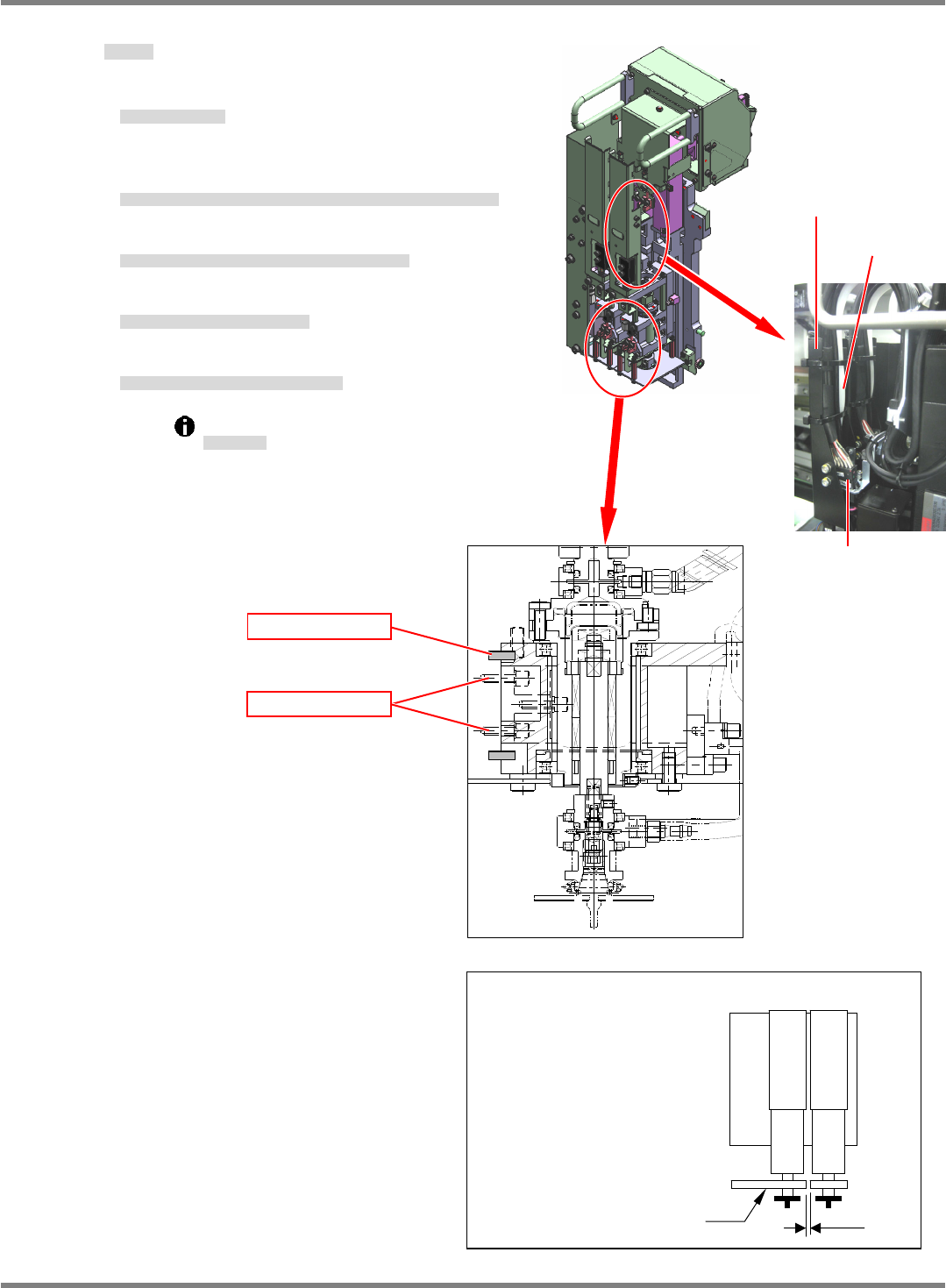
1. Attach the head unit.
ユニット交換します。
交换装置。
2. Align the head unit with the 4 positioning pin and lock in
place with the screws (4-M3). (Figs. 1 and 2)
ユニットを
4
規正ピンに合わせてボルト
(4-M3)
で固定します。
(Figs. 1 and 2)
将装置对准4 调整销,用螺钉 (4-M3) 固定住。(Figs. 1 and 2)
3. Connect the air and vacuum tubes. (Fig. 1)
エアー用チューブ
/
真空用チューブを差し込みます。
(Fig. 1)
插入空气用软管 / 真空用软管。(Fig. 1)
4. Connect connectors to the head unit.
ユニットのコネクタ接続を接続します。
连接装置的连接器。
5. Attach the reflector and check for gapping. (Fig. 3)
反射板を取り付け、隙間を確認します。
(Fig. 3)
安装反射板后,确认间隙。(Fig. 3)
Reflector gapping should be 0.2 to 0.5 mm.
反射板の隙間
反射板的间隙
Check for gapping in the reflector after installing transfer head
Reflector
B
Reflector gapping 0.2 to 0.5 mm
(To be stopped when T is 0.5)
Fig. 3
Air tube
Vacuum tube
Connector
Fig. 1
Fig. 2
Lock bolt (4-M3)
4 positioning pin