NPM-D3维修手册.pdf - 第171页
NPM-D3 Service Manual 5.4 2-nozzle Head EJM6D3-MB-05SM-00( 編集中 ).DOC Page 5-43 5.4.4 Z-axis Motor Replacement Z モータ交換 Z 电机的交换 Unit No. N610069507AA 5.1.1 Head Unit Detaching an d Attaching ヘッドユニット取り外し / 取り付け 头装置的拆卸和安装 5.…
NPM-D3
Service Manual
5.4 2-nozzle Head
Page 5-42 EJM6D3-MB-05SM-00(
編集中
).DOC
Axis Motor Attaching
取り付け
安装
18.
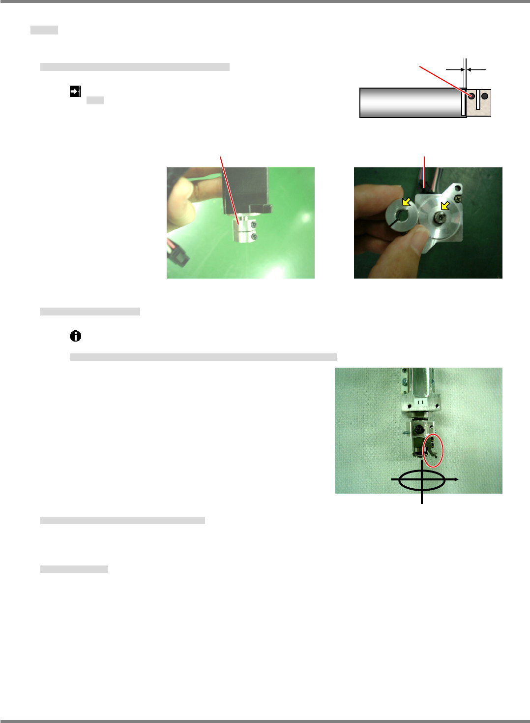
1. Attach the motor and tighten the coupling. (1 bolt on motor side)
モータを交換して、カップリングを締めます。(モータ側のボルト 1 本)
交换电机后,拧松联轴器。(电机侧的 1 根螺栓)
Clearance: 0.4 ~ 0.6 mm
すき間
间隙
2. Attach the motor and tighten the coupling.
モータを付けカップリングを締める。
安装电机后,拧紧联轴器。
Turn the holder to the
origin position (nozzle guide comes to right when viewed from front)
and tighten the coupling.
ホルダを
原点位置
(
正面から見て右側にノズルガイドがくる位置
)
に回してカップリングを締める。
将支架转动到
原点位置
(
从正面看,右侧有吸嘴导轨的位置
)
后,拧紧联轴器。
3. Attach the cover and anchor connectors with cable ties.
カバーを取り付け、コネクタをインシュロックで結束します。
安装盖后,用捆束带固定连接器。
4. Attach the
unit.
ユニットを取り付ける。
安装
装置。
‘
Unit Replacement Procedure’.
0.4 ~ 0.6 mm
Bolt
Check for the notch and origin of the coupling.
Screws on the right side
NPM-D3
Service Manual
5.4 2-nozzle Head
EJM6D3-MB-05SM-00(
編集中
).DOC Page 5-43
5.4.4 Z-axis Motor Replacement
Z モータ交換
Z 电机的交换
Unit No.
N610069507AA
5.1.1 Head Unit Detaching and
Attaching
ヘッドユニット取り外し
/
取り付け
头装置的拆卸和安装
5.4.4 Z-axis Motor Replacement
Z
モータ交換
Z
电机的交换
Z-axis Motor Detaching
取り外し
拆卸
19.
1. Detach the head unit.
ヘッドユニットを取り外します。
卸下头装置。
‘Head Unit Replacement Procedure’.
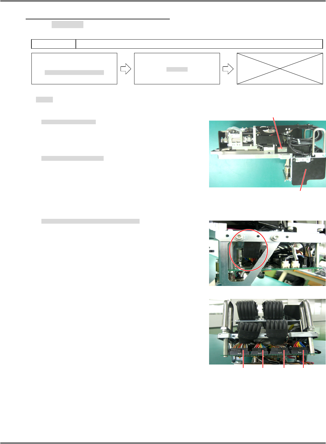
2. Detach the board cover. (Fig. 1)
基板部カバーを取り外します。(Fig. 1)
拆下基板部的盖。(Fig. 1)
3. Disconnect the Z-axis motor connectors (CN1 and CN3). (Figs. 2 and 3)
Z モータのコネクタを抜きます。(CN1 / CN3) (Figs. 2 and 3)
拔出 Z 电机的连接器。(CN1 / CN3) (Figs. 2 and 3)
Z-axis motor
Head board cover
Fig. 1
Fig. 2
Fig. 3
CN4 CN3 CN2 CN1
NPM-D3
Service Manual
5.4 2-nozzle Head
Page 5-44 EJM6D3-MB-05SM-00(
編集中
).DOC
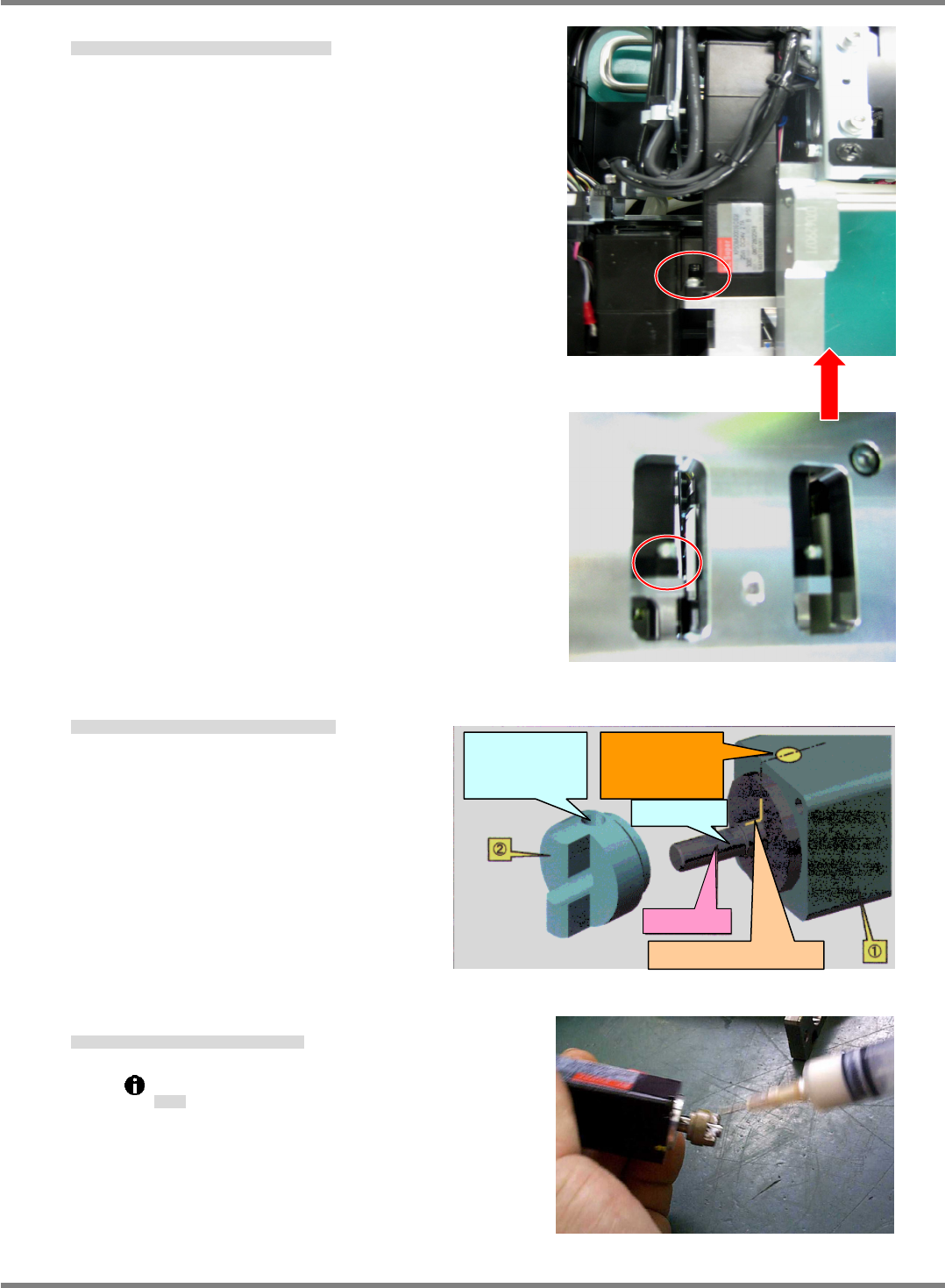
4. Detach the Z-axis motor (2-M4 bolts). (Figs. 4 and 5)
Z モータを取り外します。(ボルト 2-M4) (Figs. 4 and 5)
卸下 Z 电机。(螺栓 2-M4) (Figs. 4 and 5)
5. Remove the setscrew and replace the joint. (Fig. 6)
セットビスを外し、ジョイントを付け替えます。(Fig. 6)
拧下定位螺钉后,换上接头。(Fig. 6)
6. Thinly grease the joint. (Fig. 7)
ジョイント部にグリスを少量塗布します。(Fig. 7)
在连接部涂敷少量的润滑脂。(Fig. 7)
Grease: Panasonic LCG100
グリス
润滑脂
Fig. 7
Fig. 4
One bolt is located on the rear side.
Fig. 5
Fig. 6
Motor shaft
A: Mark by manufacturer
D: Align the hollow
set screw hole of
(2) with the D-cut
of (1).
C: D-cut plane
B: Yellow marking
on the side of (1)
for easy finding of
the position A.