NPM-D3维修手册.pdf - 第223页
NPM-D3 SERVICE MANUAL 6.1 Control System Configuration EJM6D3-MB-06SM-00( 編集中 ).DOC Page 6-3 6.1.2 Control Unit Arrangement 配置図 配置图 Operation switch board (PNF0A5-AA) N610073212AB Power unit N610058919AE Ring I/O load bo…
NPM-D3
SERVICE MANUAL
6.1 Control System Configuration
Page 6-2 EJM6D3-MB-06SM-00(
編集中
).DOC
6.1 Control System Configuration
制御システム体系
控制系统体系
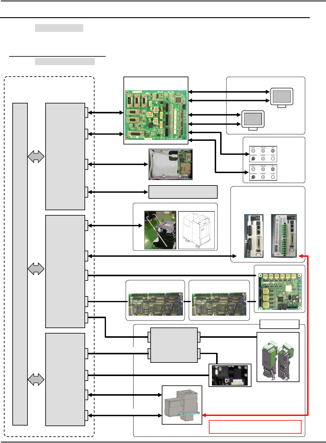
6.1.1 Block Diagrams
制御システムブロック図
控制系统结构图
Operation switchboard
Analog
RGB
USB
Feeder
RS422
ILK board #1
Ring I/O load board
Touch screens
RS232C
Front
Rear
Analog RGB
Drivers
X axis
400 W
X axis
750 W
SW panels
Front
Rear
Same system also on the rear side.
RS232C
Analog RGB
Head
Compact PCI
board computer
(CPU board)
LAN
RS232C
Optical ring
Camera link
PC board camera & LED lighting
ILK, +24V, S422
Camera link
P9 controller
PCI bus ( 32 bit / 33 MHz )
Front side
Axes &
I/O board
Camera I/F
board
(Recognition
board)
Lighting
control board
To LNB station
ILK board #2
RS422 // I/O 1bit
I/O, +24V, RS422
NPM-D3
SERVICE MANUAL
6.1 Control System Configuration
EJM6D3-MB-06SM-00(
編集中
).DOC Page 6-3
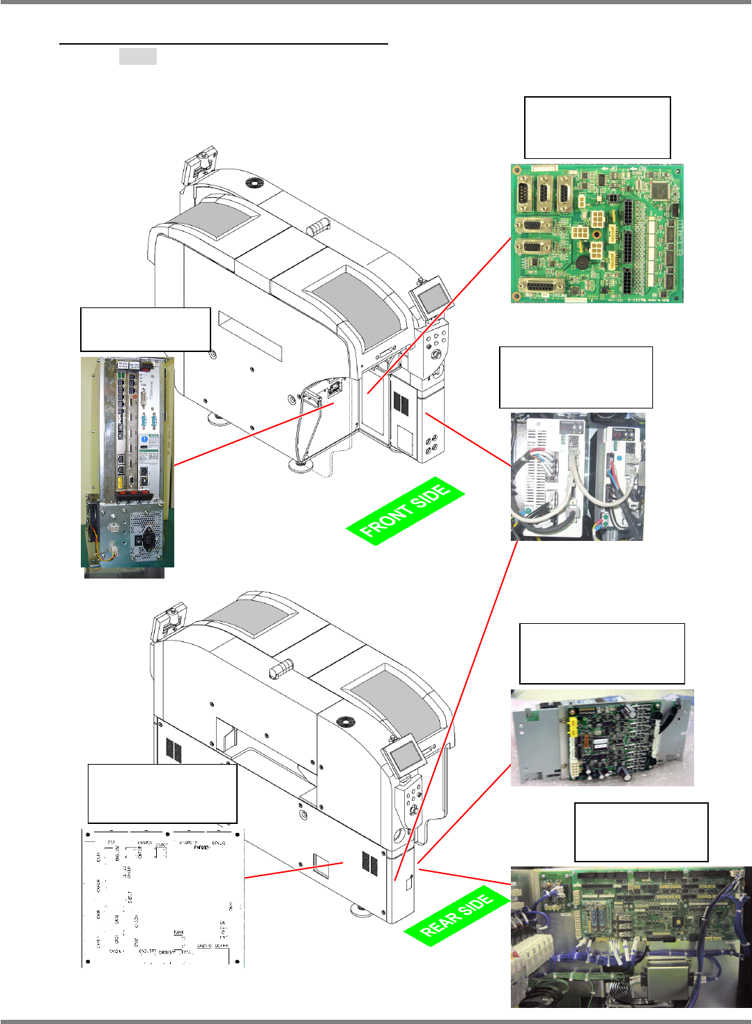
6.1.2 Control Unit Arrangement
配置図
配置图
Operation switch
board (PNF0A5-AA)
N610073212AB
Power unit
N610058919AE
Ring I/O load board
PNF0B3-AA
N610113311AA
Support driver unit
N510036332AA
P9 controller
N610073583AA
XY drivers
X: MCDHT3520NL3
Y: MEDHT7364NL3
NPM-D3
SERVICE MANUAL
6.1 Control System Configuration
Page 6-4 EJM6D3-MB-06SM-00(
編集中
).DOC
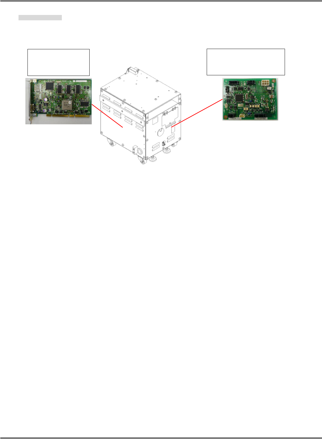
Check Box (Option)
検査 BOX (オプション)
检查 BOX (选购件)
Camera IF board
(PPR0AE-AA)
N610081331AA
Head communication
relay board (PNF0AP-AA)
N610102517AA