NPM-D3维修手册.pdf - 第226页
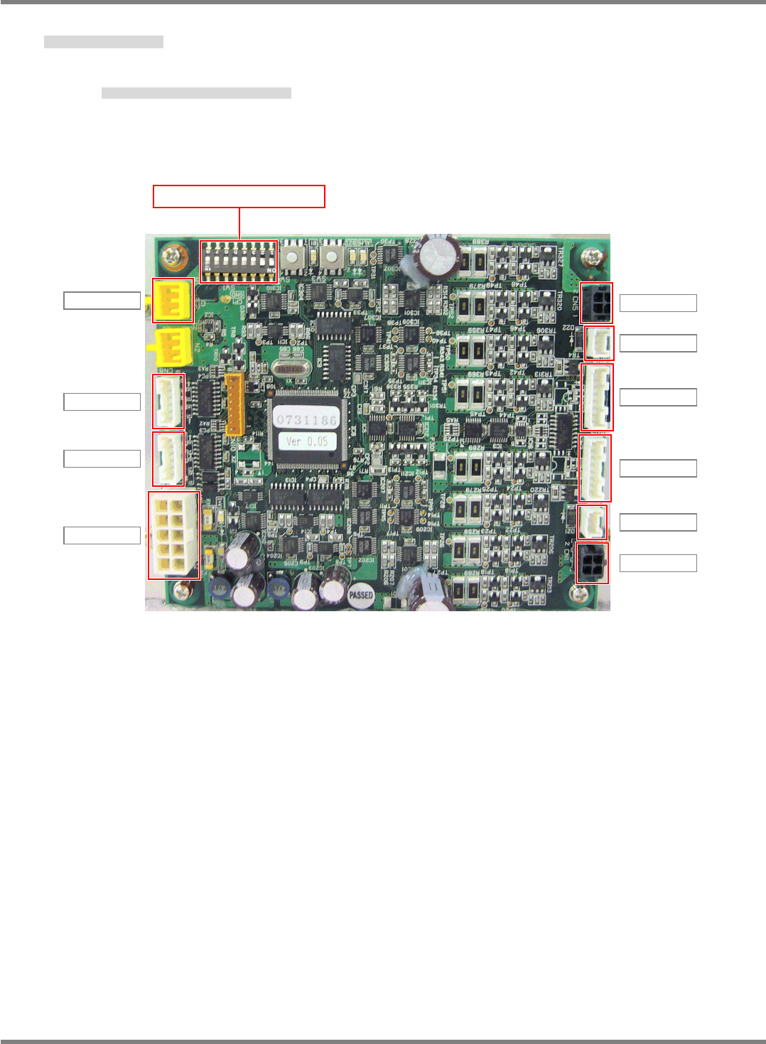
NPM-D3 SERVICE MANUAL 6.1 Control System Configuration Page 6-6 EJM6D3-MB-06SM-00( 編集中 ).DOC Support Driver Unit 下受けドライバーユニット 支撑驱动器装置 Functions: Controls the support motor. 機能 : 下受けモータのコントロールを行います。 功能 : 进行支撑电机的控制。 CN1K…
NPM-D3
SERVICE MANUAL
6.1 Control System Configuration
EJM6D3-MB-06SM-00(
編集中
).DOC Page 6-5
6.1.3 Description
ボード説明
板的说明
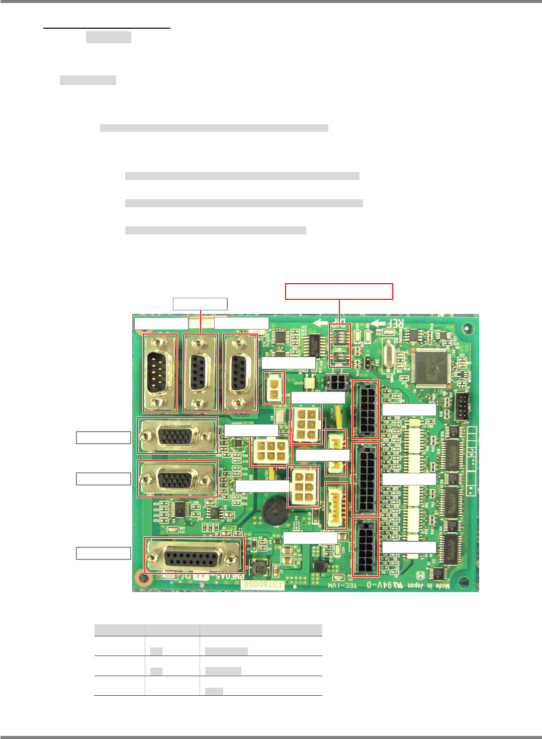
Operation Switch Board
操作切換えボード
操作切换板
Functions: Handles the inputs from the sheet keys on the control panel and changes over the
active touch screen (between front and rear).
機能
:
操作パネル
シートキーの入力、および前後タッチパネルの切り替えを行う。
功能
:
进行操作面板
薄膜软键的输入、以及前后触摸屏的切换。
Notifies the host CPU (P9) of the operation switches or adjacent I/O information via the
RS-232C port.
操作スイッチ、隣接 I / O の情報を、RS-232C を介してホスト CPU (P9) に通知する。
操作开关和邻接 I / O 的信息,通过 RS-232C 通知给主机 CPU (P9)。
Notifies the CPU (P9) of the touch screen data entered via the RS-232C port.
入力されたタッチパネルのデータを、RS-232C を介してホスト CPU (P9) に通知する。
将所输入的触摸屏的信息,通过 RS-232C 通知给主机 CPU (P9)。
Enables and disables the front/rear touch screen keys and the operation key switches.
フロント・リアのタッチパネル、操作キーの有効、無効を制御する
控制 FRONT 和 REAR 的触摸屏,以及操作键的有效和无效。
Condition of LED
No. OK Contents
LED1
Lighting
点灯
12V power monitoring
12V
電源モニタ
LED2
Flashing
点滅
Firmware running
ファーム動作
LED3
-
No use
未使用
CN11K328
CN10K328
CN12K328
CN13K328
CN7K328
CN14K328
CN9K328
CN15K328
CN8K328
CN1K328
CN2K328
CN3K328
CN4K328
CN6K328
CN5K328
All DIP switches: OFF
NPM-D3
SERVICE MANUAL
6.1 Control System Configuration
Page 6-6 EJM6D3-MB-06SM-00(
編集中
).DOC
Support Driver Unit
下受けドライバーユニット
支撑驱动器装置
Functions: Controls the support motor.
機能
:
下受けモータのコントロールを行います。
功能
:
进行支撑电机的控制。
CN1K621
CN2K621
CN3K621
CN7K621
CN6K621
CN5K621
CN1K621
CN8K621
CN4K621
CN9K621
DIP SW: 1,2 ON
NPM-D3
SERVICE MANUAL
6.1 Control System Configuration
EJM6D3-MB-06SM-00(
編集中
).DOC Page 6-7
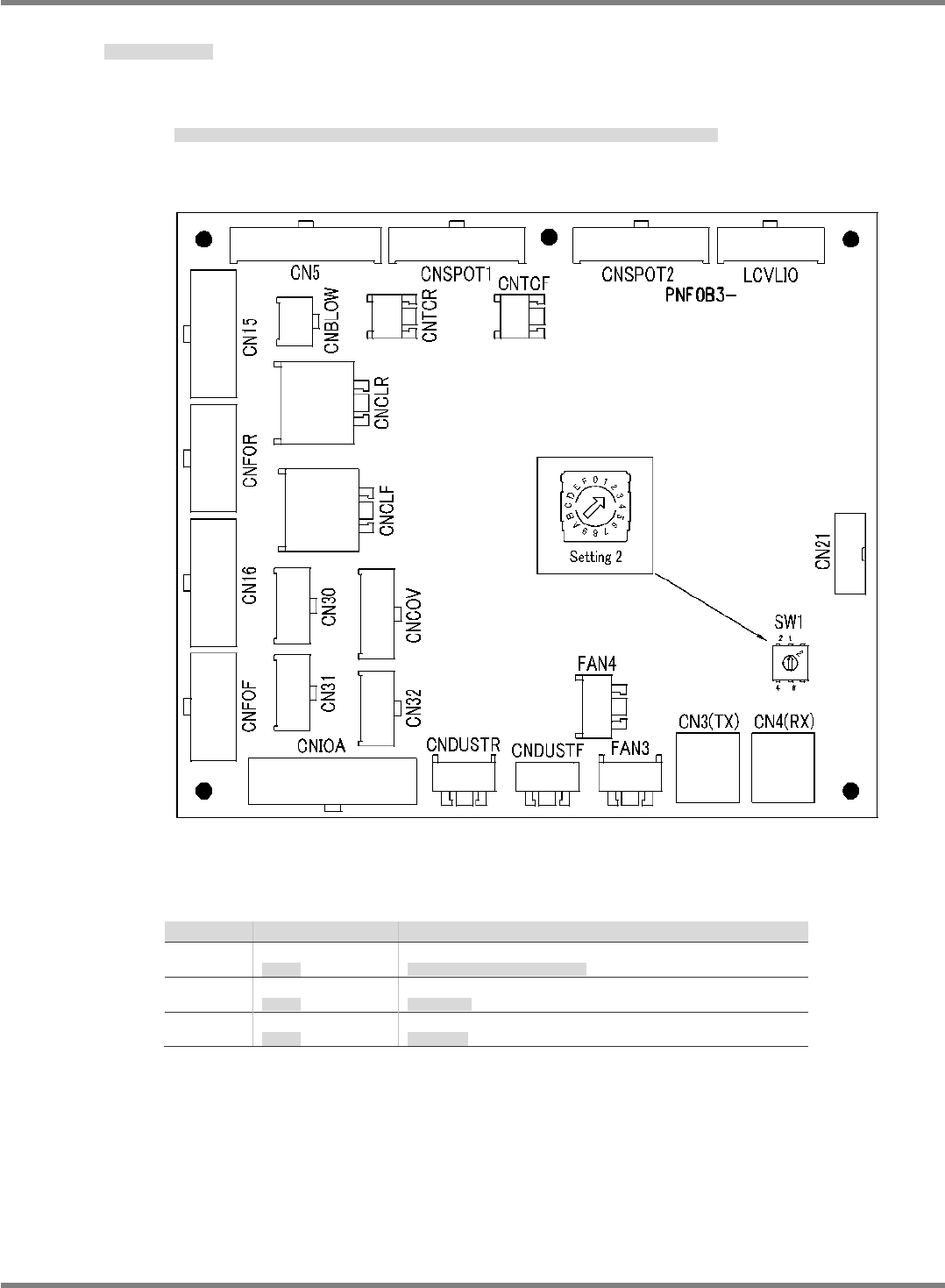
Ring I/O Load Board
リング I/O 負荷基板
环 I / O 负荷基板
Functions: I/O load board mounted on the axis and I/O control board (PNF0B3-AA) of P9
controller is used for the ring communication.
機能
: P9
コントローラの軸&
I/O
制御ボード
(PNF0B3-AA)
に搭載された
Ring
通信に接続される
I/O
負荷ボード。
功能
:
连接到
P9
控制器的轴&
I/O
控制板
(PNFB3-AA)
上搭载的
Ring
通信的
I/O
负荷板。
Condition of LED
No. OK Contents
LED1
Unlit (Red)
消灯
(
赤
)
LED turns on at initializing FPGA. Usually It turns off.
FPGA
初期化時に点灯し、通常は消灯
LED2
Lighting (Green)
点灯
(
緑
)
3.3V powered on
3.3V
電源
ON
LED3
Lighting (Green)
点灯
(
緑
)
24V powered on
24V
電源
ON