NPM-D3维修手册.pdf - 第239页
NPM-D3 SERVICE MANUAL 6.2 P9 Controller EJM6D3-MB-06SM-00( 編集中 ).DOC Page 6-19 Maintenance メンテナンス 维修 The NC and I/O board has a battery. Basically, it lasts more than 10 years with power off. However, in cas e of unexp…
NPM-D3
SERVICE MANUAL
6.2 P9 Controller
Page 6-18 EJM6D3-MB-06SM-00(
編集中
).DOC
Remarks
補足説明
补充说明
The battery of this board keeps the currently used machine parameters.
If an unexpected accident occurs due to deteriorated battery, a battery warning is given.
Reload the data from the compact PCI board computer or the PT.
NC
I / O
ボードのバッテリにて、現在稼動中のマシンパラメータが保存されています。
バッテリが劣化し不測の事態が発生した場合、バッテリアラーム警告が出ます。
コンパクト
PCI
ボードコンピュータ、
PT
などに保存されているデータを再ロードしてください。
用
NC
I / O
板的电池,现在运转中的机器参数被保存。
因电池的劣化而引起不测事态时,电池会发出警报。
请再次下载在小型
PCI
板电脑、
PT
等中保存的数据。
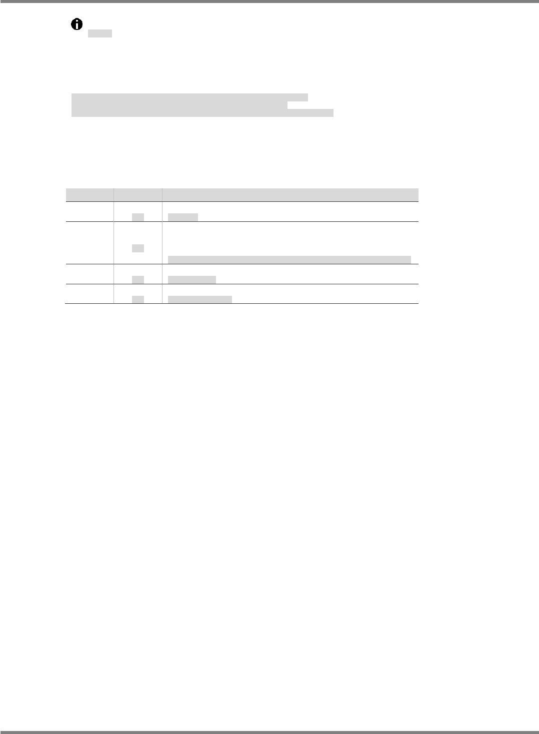
No. OK
内容
LED1
Flashing
点滅
Head communication is OK.
ヘッド通信
LED2
Lighting
点灯
Ring I/O communication is OK. (When it is a trouble,
please check the Optical communication cable and
connection.
)
リング
I/O
通信
(
異常時は光通信ケーブルの接続、光通信ケーブルそのものの異常を確認。
)
LED3
Unlit
消灯
Starting up NC/IO board
NC/IO
ボード起動
LED4
Lighting
点灯
NC firmware is OK.
NC
ファームウエア動作
NPM-D3
SERVICE MANUAL
6.2 P9 Controller
EJM6D3-MB-06SM-00(
編集中
).DOC Page 6-19
Maintenance
メンテナンス
维修
The NC and I/O board has a battery.
Basically, it lasts more than 10 years with power off. However, in case of unexpected accidents,
replacement procedure is given below.
本軸
I/O
制御ボードには、電池が載っています。
基本的には、無通電状態で
10
年以上の寿命を持っています。しかしながら不測の事態が発生した場合を想定し、交換手順を以下に示します。
在本轴
I/O
控制板上搭载电池。
基本上,在非通电状态下可用
10
年以上。但为了以备不测,更换步骤如下所示。
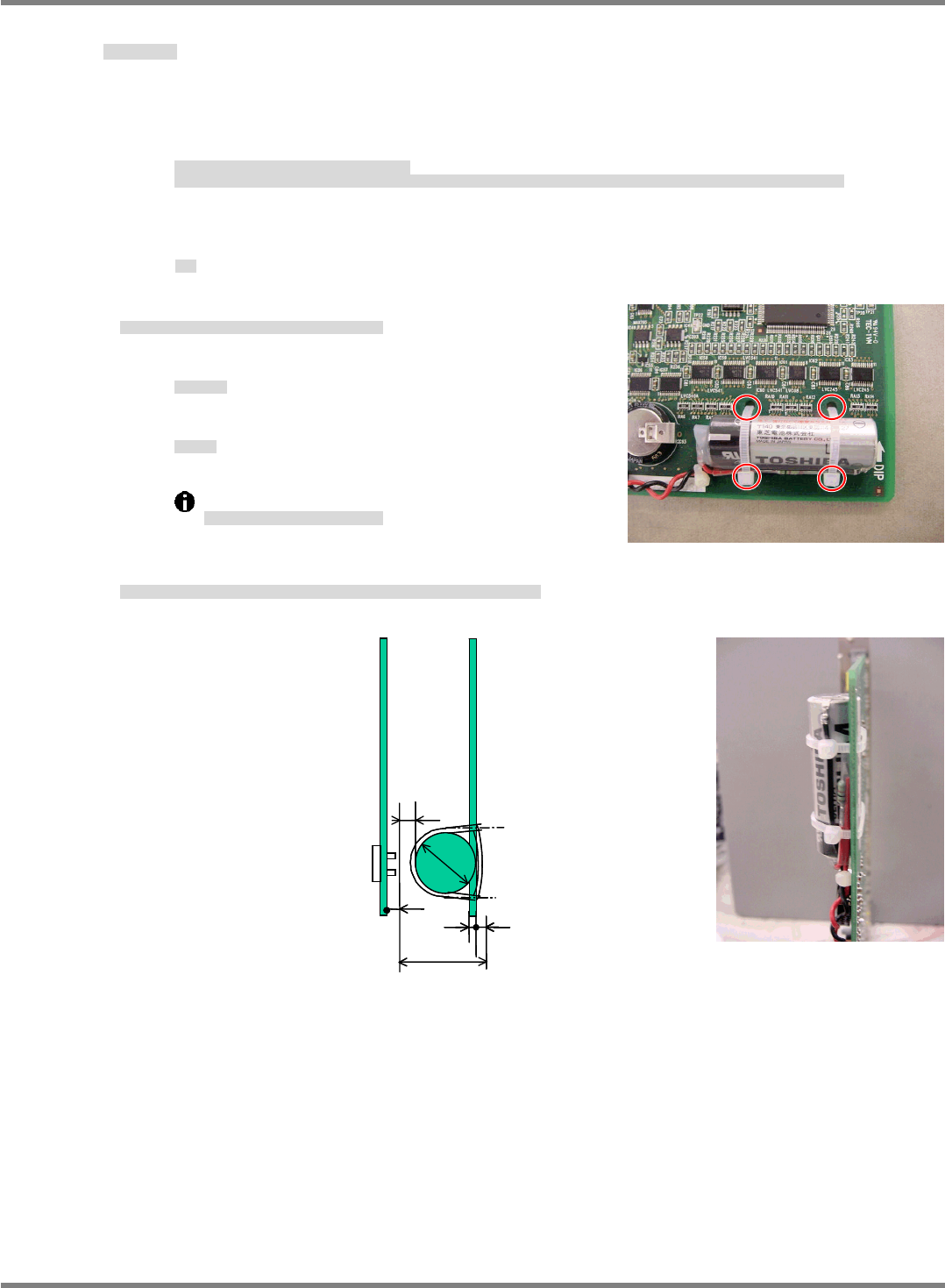
Procedure
手順
步骤
2.
1. Disconnect the cable from the connector. Cut the cable tie.
ケーブルをコネクタから外し、結束バンドを切ります。
从连接器上取下电缆,切断捆束带。
Cable tie: AB100-W (Tyton)
結束バンド
捆束带
Battery :
N610156136AA
バッテリ
电池
Please replace the battery within two hours.
作業は 2 時間以内で行ってください。
请在 2 小时内完成作业。
2. Replace the battery. Secure it with cable ties. For battery position, see below.
電池を交換し、結束バンドで固定します。その際、電池固定は下記寸法を満足すること。
交换电池后,用捆束带固定。此时,电池固定应满足下列的尺寸。
1.6 mm
14
mm
4.32 mm
20.32 mm
7 mm
14
mm
2 mm
PC
board
(Compact PCI slot width)
Gap with the live parts on the adjacent board
NPM-D3
SERVICE MANUAL
6.2 P9 Controller
Page 6-20 EJM6D3-MB-06SM-00(
編集中
).DOC
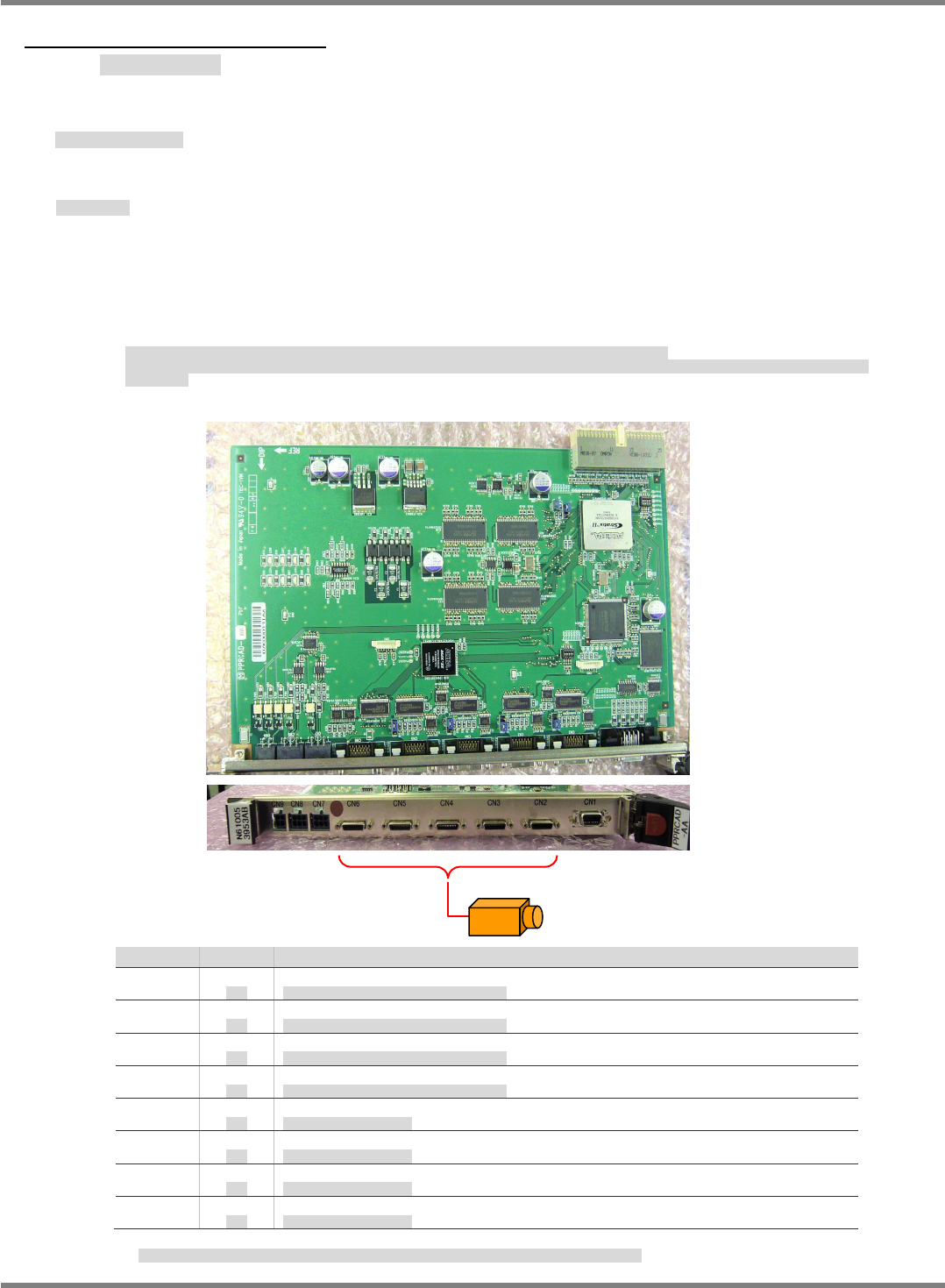
6.2.4 Camera I/F Board
カメラ I/F ボード
照相机 I/F 板
Name: Camera I/F board (Model: PRCAD-AA Part No.:
N610053953AC
)
名称
:
カメラ
I/F
ボード
名称
:
照相机
I/F
板
Basic Specifications
基本スペック
基本规格
This board interfaces with the recognition modules such as cameras and line sensors. It has no
CPU.
As the recognition monitor function, the board transfers the image data captured by cameras to
the CPU board (NBC
JC154X
D5) via the internal bus. The data is superimposed on the control
panel display by the CPU board.
カメラ、ラインセンサなどの認識モジュールのインターフェイス機能を有するボードで、内部に
CPU
を持たない。
認識モニタ機能は、カメラから取り込まれた画像データを内部バスで
CPU
ボード
(NBC
JC154X
D5)
に転送し、
CPU
ボードから操作盤表示を行う際、イン
ポーズする。
本板备有照相机、线性传感器等的识别模块的界面功能,内部没有
CPU
。
识别监视功能是,用内部总线,从照相机获取的画像数据传送给
CPU
板
(NBC
JC154X
D5)
,并从
CPU
板进行操作盘的显示时,将画面叠加显示。
No. OK 内容
LED1
Unlit
消灯
Checking the CH2 Camera cable disconnecting
CH2
に接続するカメラケーブルの断線チェック
LED2
Unlit
消灯
Checking the CH3 Camera cable disconnecting
CH3
に接続するカメラケーブルの断線チェック
LED3
Unlit
消灯
Checking the CH4 Camera cable disconnecting
CH4
に接続するカメラケーブルの断線チェック
LED4
Unlit
消灯
Checking the CH5 Camera cable disconnecting
CH5
に接続するカメラケーブルの断線チェック
LED5
Unlit
消灯
Power supply for CH2 Camera
CH2
のカメラへの電源供給
LED6
Unlit
消灯
Power supply for CH3 Camera
CH3
のカメラへの電源供給
LED7
Unlit
消灯
Power supply for CH4 Camera
CH4
のカメラへの電源供給
LED8
Unlit
消灯
Power supply for CH5 Camera
CH5
のカメラへの電源供給
When the image is loaded, LED1-4 disconnecting is checked. And only Clock signal cable is checked.
LED1~4
の断線チェックはカメラ画像の取り込み中にのみ機能し、チェックするのはクロック線のみです。
Fixed camera / Head camera