NPM-D3维修手册.pdf - 第59页
NPM-D3 SERVICE MANUAL 4.2 XY Drive Axes EJM6D3-MB-04SM-02.DOC Page 4-21 (B) (A) Fig. 4 6. Attach the stator. (Figs. 2 and 3) 固定子の取り付け。 (Fig. 2, Fig. 3) 安装固定子。 (Fig. 2, Fig. 3) Move the head plate to the end side and atta…
NPM-D3
SERVICE MANUAL
4.2 XY Drive Axes
Page 4-20 EJM6D3-MB-04SM-02.DOC
4.2.5 Linear Motor Replacement
リニアモータ交換
线性电机的交换
Unit No.
N610052923AA
N610052924AA
Safety
Process
4.2.5 Linear Motor Replacement
リニアモータ交換
线性电机的交换
4.2.1 Linear Scale Adjustment
リニアスケールの調整
线性刻度的调整
4.2.2 Origin Adjustment
原点調整
原点调整
X-axis Linear Motor Replacement
X 軸リニアモータ交換
X 轴线性电机的交换
6.
1. Turn OFF the power and air.
電源・エアーを OFF にします。
将电源和空气置于 OFF。
2. Detach the head.
ヘッドを外します。
卸下头。
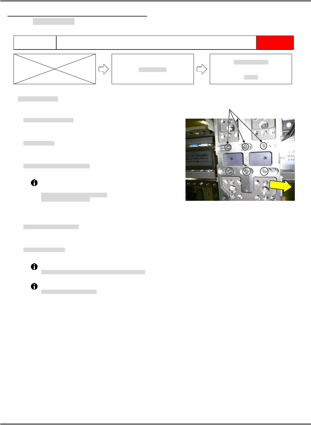
3. Detach the linear motor stators. (Fig. 1)
リニアモータの固定子を外します。(Fig. 1)
卸下线性电机的固定子。(Fig. 1)
Handle the stators with due care.
Use the stator cover.
固定子の取り扱いには充分注意すること。
固定子カバーを使用すること。
对固定子的使用处理要充分注意。
要使用固定子盖。
4. Detach the linear motor movers.
リニアモータの可動子を外します。
拆下线性电机的可动子。
5. Attach the mover.
可動子を取り付けします。
安装可动子。
Insert a 1 mm thickness gauge at the lower part.
取り付け下部に
1 mm
のシクネスゲージをはさんで、取り付ける。
在安装的下部夹入
1 mm
的间隙规后进行安装。
Be careful not to tilt it.
傾かないように注意してください。
请注意不要倾斜。
Fig. 1
Bolt
NPM-D3
SERVICE MANUAL
4.2 XY Drive Axes
EJM6D3-MB-04SM-02.DOC Page 4-21
(B)
(A)
Fig. 4
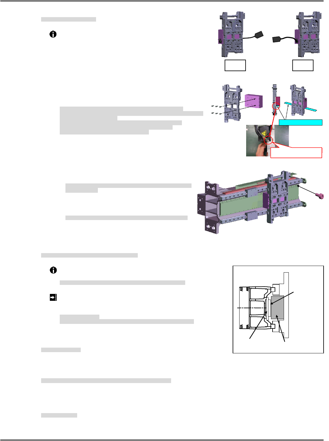
6. Attach the stator. (Figs. 2 and 3)
固定子の取り付け。(Fig. 2, Fig. 3)
安装固定子。(Fig. 2, Fig. 3)
Move the head plate to the end side and attach the
Y-axis side stator (A) first.
Face the side with the S and N polarity labels
downward, press the stators from above against the
steps in the X-beam, and fix then at the center of the
mounting holes.
Attach the stators so that the S mark moves in the (+)
direction on both the front and rear.
Move the head plate to the opposite side and fix the
other stator.
Attach the rear side stator (B) (A) in the same way.
ヘッドプレートを先端側に寄せ、
Y
軸側の固定子
(A)
を先に取り付けます。
S
極、
N
極のシールがある方を下側にして、
X
ビームの段つきに上から下に押しあて、取
り付け穴のセンターで固定します。
FRONT
・
REAR
とも
S
マークが
(+)
移動方向になるように取り付けます。
ヘッドプレートを反対側に寄せてもう一枚の固定子
(A)
を固定します。
REAR
側の固定子
(B)(A)
も同じように取り付けます。
将头板靠在端部侧,在端部侧安装
Y
轴侧的固定子
(A)
。
有向均匀地安装。将
S
极、
N
极的有标签的一侧向下侧,将其从上面压在
X
轴的有层部分,
在安装孔的中心位置固定住。
FRONT
和
REAR
,都将
S
标记
()
向移动方向安装。
将头板靠在相反侧后,固定另一个的固定子。
REAR
侧的固定子
(B)(A)
也同样地安装。
When moving the plate, note that it moves
swiftly due to the magnet force of the stator (B).
プレートを移動する際、B 固定子の磁力にてプレートが勢いよく移動するので、
注意してください。
移动板时,会因为 B 定子的磁性而使板强力移动,所以请注意。
When attaching the stator (A), note that the
stators strongly attract each other.
A 固定子取り付け時、固定子同士が強烈に引き合うので注意してください。
安装 A 固定子时,定子之间会强力吸引,请注意。
7. Check the clearance between the stators and movers of the linear motor. (Fig. 5)
リニアモータの固定子と可動子の GAP を確認する。(Fig. 5)
确认线性电机的固定子和可动子的 GAP。(Fig. 5)
Check the clearance across the full stroke of the front and rear
axes using a thickness gauge.
F
軸・
R
軸のストローク全域でシックネスゲージにて、すき間を確認します。
在
F
轴、
R
轴的整个行程上,用间隙规确认间隙。
Clearance between stators and movers: 0.1 to 0.5 mm
(A 0.1 mm thickness gauge should pass but not a 0.6 mm
gauge.)
固定子と可動子のスキマ
(0.1mm
のシックネスゲージが通り、
0.6mm
のシックネスゲージが通らないこと。
)
固定子和可动子的间隙
(0.1 mm
的间隙规可通过,
0.6 mm
的间隙规不可通过。
)
8. Attach the head.
ヘッドを取り付けます。
安装头。
9. Turn ON the power and air, and adjust the X-axis linear scale and
X-axis origin.
電源・エアーを ON にし、X 軸リニアスケール調整と X 軸原点調整を行います。
将电源和空气置于 ON,进行 X 轴线性刻度的调整和 X 轴原点调整。
‘4.2.1 Linear Scale Adjustment’ and ‘4.2.2 Origin Adjustment’.
10. Perform teaching.
ティーチを行います。
进行示教。
Fig. 2
Front
Rear
Fig. 3
1 mm thickness
g
au
g
e
Place the thickness gauge
properly.
GAP確認
固定子
可動子
GAP確認
固定子
可動子
(Fig. 5)
Clearance
check
Mover
Stator
NPM-D3
SERVICE MANUAL
4.2 XY Drive Axes
Page 4-22 EJM6D3-MB-04SM-02.DOC
Y-axis Linear Motor Replacement
Y 軸リニアモータ交換
Y 轴线性电机的交换
7.
1. Turn OFF the power and air.
電源・エアーを OFF にします。
将电源和空气置于 OFF。
2. Detach the linear motor movers.
リニアモータの固定子を外します。
卸下线性电机的可动子。
3. Detach the linear motor movers.
リニアモータの可動子を外します。
拆下线性电机的可动子。
4. Attach the mover.
可動子を取り付けします。
安装可动子。
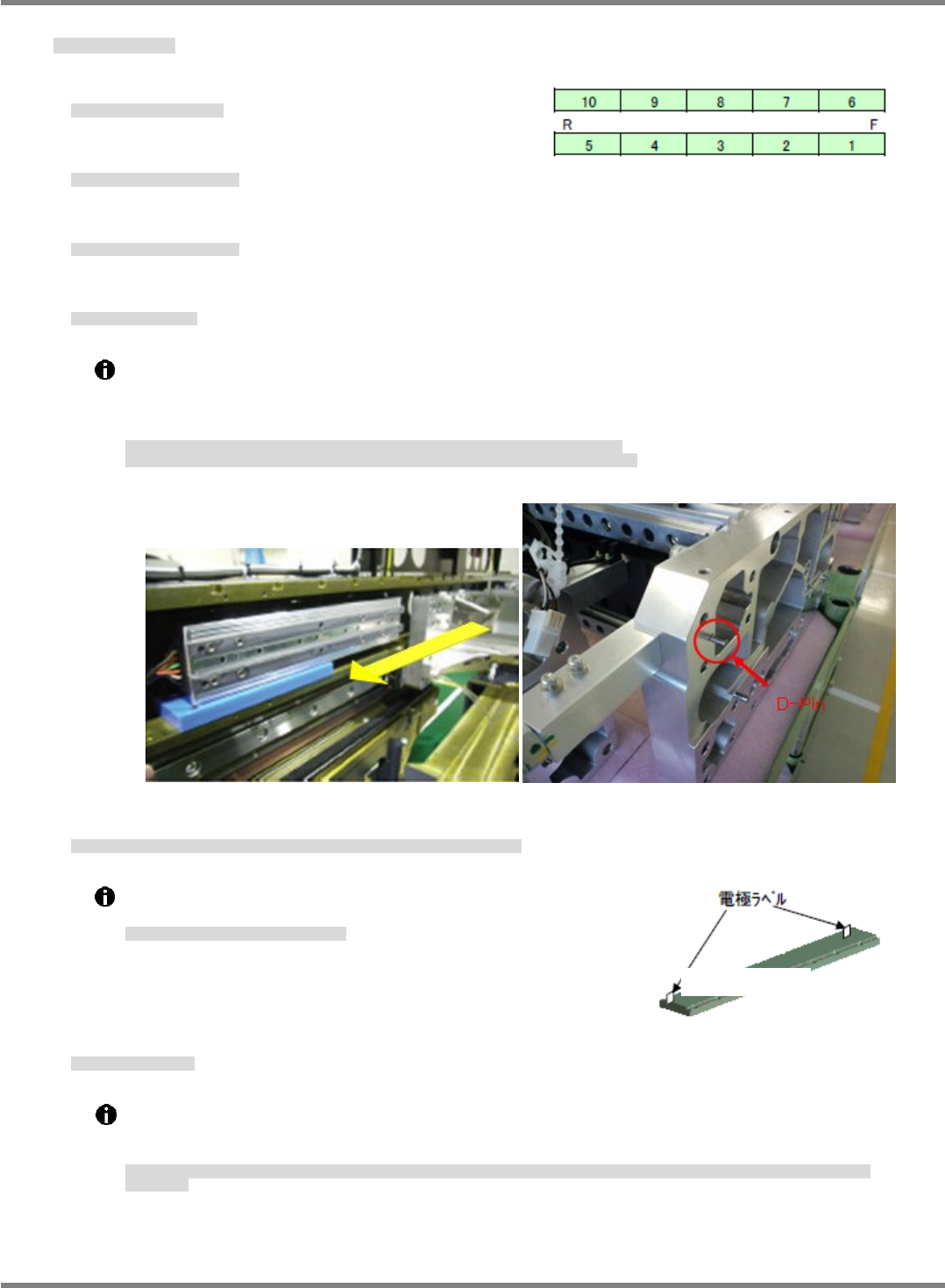
With the cables facing outward (on both the front and rear), place the mover mounting jig and set
the mover on it.
Slide the X beam to adjust the mounting hole position so that the D-pin may fit the mover, and
secure the beam in place.
ケーブルの向きに注意し
(F
、
R
とも外向き
)
、可動子取り付けジグを置いて、その上に可動子をのせる。
X
ビームをスライドさせ、
X
ビームへ
D-pin
が可動子に入るように、取り付け穴の位置を合わせて固定する。
请注意电缆的朝向
(F
、
R
都朝外
)
,放好可动子安装治具后,将可动子放在其上面。
使
X
臂滑动,对准安装孔的位置,使
D-pin
能向
X
臂进入到可动子中,然后固定住。
5. Attach the new stators in the order of 1, 2, 6, 7, 3, 4, 5, 8, 9 and 10 as shown in Fig. 5.
新しい固定子を Fig. 5 の固定子番号 1、2、6、7、3、4、5、8、9、10 の順で取り付けします。
将新的固定子,按照 Fig. 5 的固定子编号 1, 2, 6, 7, 3, 4, 5, 8, 9, 10 的顺序安装。
Do not move the beam until all the stators (upper and lower sides)
are attached.
上下を取り付けてからビームを移動すること。
安装了上面和下面后才移动臂。
6. Attach stator No. 1.
1 番の固定子の取り付け。
安装 1 号的固定子。
Attach the protective cover to the stator and face the electrode label to the rear. Locate the
installation hole centers and, while pressing the stator against the frame, tighten first the end
bolts and then all bolts to lock down.
固定子に保護カバーを取り付け、電極ラベルを奥側に向け、取り付けの中心を目測し、フレーム奥に押し当てながら両端のボルトで固定してから全てのボルト
を固定する。
将保护盖安装在固定子上,使电极标签朝向内侧,目测安装的中心,一边推压到框架内侧,一边用两端的螺栓固定后,再固定全部的螺栓。
Fig. 6
Fig. 7
Fig. 8
Fig. 9
Electrode label