NPM-D3维修手册.pdf - 第62页
NPM-D3 SERVICE MANUAL 4.3 Feeder Cart Unit Page 4-24 EJM6D3-MB-04SM-02.DOC 4.3 Feeder Cart Unit 交換台車部 交换台车部 4.3.1 Feeder Cart Handling Unit 交換台車駆動ユニット 交换台车驱动装置 Unit No. N610060938AA (Front) N610060939AA (Rear) 4.3.1 Feed…
NPM-D3
SERVICE MANUAL
4.2 XY Drive Axes
EJM6D3-MB-04SM-02.DOC Page 4-23
7. Attach stator No. 2.
2
番固定子を取り付ける。
安装
2
号的固定子。
8. Attach stator No. 6.
6
番固定子の取り付け。
安装
6
号的固定子。
Attach the protective cover to the stator, set the intermediate jig on the protective cover of stator
No. 2 and set stator No. 6 with its electrode label faced to the rear. Locate the installation hole
centers and, while pressing the stator against the frame, tighten first the end bolts and then all
bolts to lock down.
Detach the intermediate jig and protective cover.
固定子に保護カバーを取り付け、
2
番固定子保護カバーの上に、中間治具を置き、
6
番固定子を電極ラベルを奥側に向けセットする。取り付け穴の中心を、フ
レーム奥に押し当てながら両端のボルトで固定してから全てのボルトを固定する。
中間治具・保護カバーを外す。
将保护盖安装在固定子上,在
2
号固定子的保护盖上放置中间治具后,将
6
号固定子以电极标签朝内进行设置。将安装孔的中心一边推压到框架内侧,一边用两端
的螺栓固定后,再固定全部的螺栓。
卸下中间治具和保护盖。
9. Attach stator No. 7.
7 番固定子を取り付ける。
安装 7 号的固定子。
10. Attach the stators in the order of 3, 4 and 5 (lower side), and 8, 9 and 10 (upper side) in the same way.
3、4、5 固定子(下側)、8、9、10 固定子(上側)の順番で順次同じように取り付けてる。
按照 3、4、5 固定子(下侧)、8、9、10 固定子(上侧)的顺序依次进行同样的安装。
11. Check the clearance between the stators and movers of the linear motor. (Fig. 10)
リニアモータの固定子と、可動子の GAP を確認する。(Fig. 10)
确认线性电机的固定子和可动子的 GAP。(Fig. 10)
Check the clearance across the full stroke of the
front and rear axes using a thickness gauge.
F
軸・
R
軸のストローク全域でシックネスゲージにてすき間を確認する。
在
F
轴、
R
轴的整个行程上,用间隙规确认间隙。
Clearance between stators and movers: 0.3 to
0.7 mm
(A 0.3 mm thickness gauge should pass but not a
0.8 mm gauge.)
固定子と可動子のスキマ
(0.3 mm
のシックネスゲージが通り、
0.8 mm
のシックネスゲージが通らないこ
と。
)
固定子和可动子的间隙
(0.3 mm
的间隙规可通过,
0.8 mm
的间隙规不可通过。
)
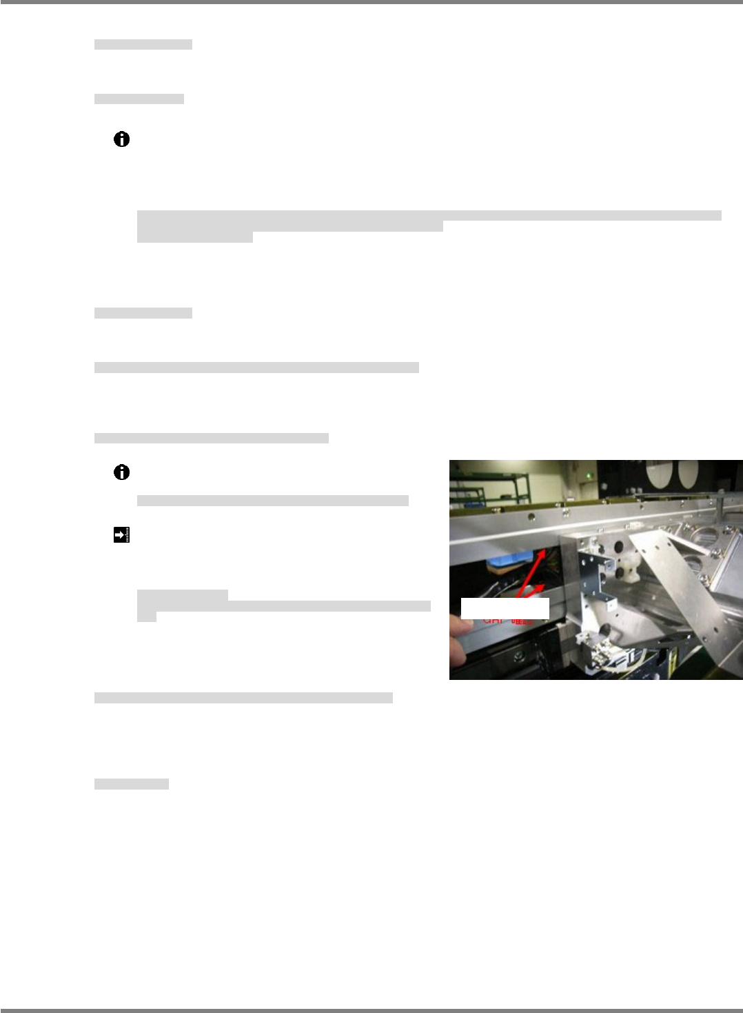
12. Turn ON the power and air, and adjust the X-axis linear
scale and X-axis origin.
電源・エアーを ON にし、Y 軸リニアスケール調整と Y 軸原点調整を行います。
将电源和空气置于 ON 后,进行 Y 轴线性刻度调整和 Y 轴原点调整。
‘4.2.1 Linear Scale Adjustment’ and ‘4.2.2 Origin Adjustment’.
13. Perform teaching.
ティーチを行います
进行示教。
Fig. 10
Clearance check
NPM-D3
SERVICE MANUAL
4.3 Feeder Cart Unit
Page 4-24 EJM6D3-MB-04SM-02.DOC
4.3 Feeder Cart Unit
交換台車部
交换台车部
4.3.1 Feeder Cart Handling Unit
交換台車駆動ユニット
交换台车驱动装置
Unit No.
N610060938AA (Front)
N610060939AA (Rear)
4.3.1 Feeder Cart Handling Unit
交換台車駆動ユニット
交换台车驱动装置
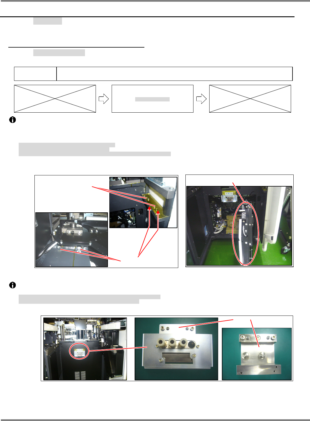
The drive unit of the feeder cart is positioned with positioning pins.
It is anchored from the bottom by bolts (2-M10 x 30). (Fig. 1)
The drive unit is more easily detached by disconnecting wiring connectors and air hoses at their relay
connections. (Fig. 2)
交換台車駆動ユニットは、規正ピンで位置決めされています。
下側からボルト
(2-M10
30)
で固定されています。
(Fig. 1)
配線コネクタとエアーホースを中継部分で外せば駆動ユニットを取り外すことができます。
(Fig. 2)
交换台车驱动装置被调整销定位。
从下面,被螺栓
(2-M10
30)
固定。
(Fig. 1)
如果在中继部分卸下配线连接器和空气软管,即可卸下驱动装置。
(Fig. 2)
The positions of connectors and air couplers connected to the feeder cart are adjusted with jigs. (Fig. 3)
Especially do not detach the air coupler block from the bracket.
交換台車との接続部のコネクタとエアーカプラの位置は治具にて調整されています。
(Fig. 3)
特に、エアーカプラのブロックは、ブラケットから取り外さないでください。
交换台车和连接部的连接器和空气耦合器的位置被治具调整。
(Fig. 3)
特别,请不要从托架上取下空气耦合器的块。
Fig. 2
Drive unit
Fig. 1
2-M10x30
Positioning pin
Fig. 3
Jig
NPM-D3
SERVICE MANUAL
4.3 Feeder Cart Unit
EJM6D3-MB-04SM-02.DOC Page 4-25
Tray Lever Backward Limit Adjustment
台車引き込みレバー後退限の調整
台车导入杆后退限的调整
Block
Caliper
ブロック
ノギス
块
游标卡尺
8.
1. Pull out the cart.
交換台車を引き出します。
拉出交换台车。
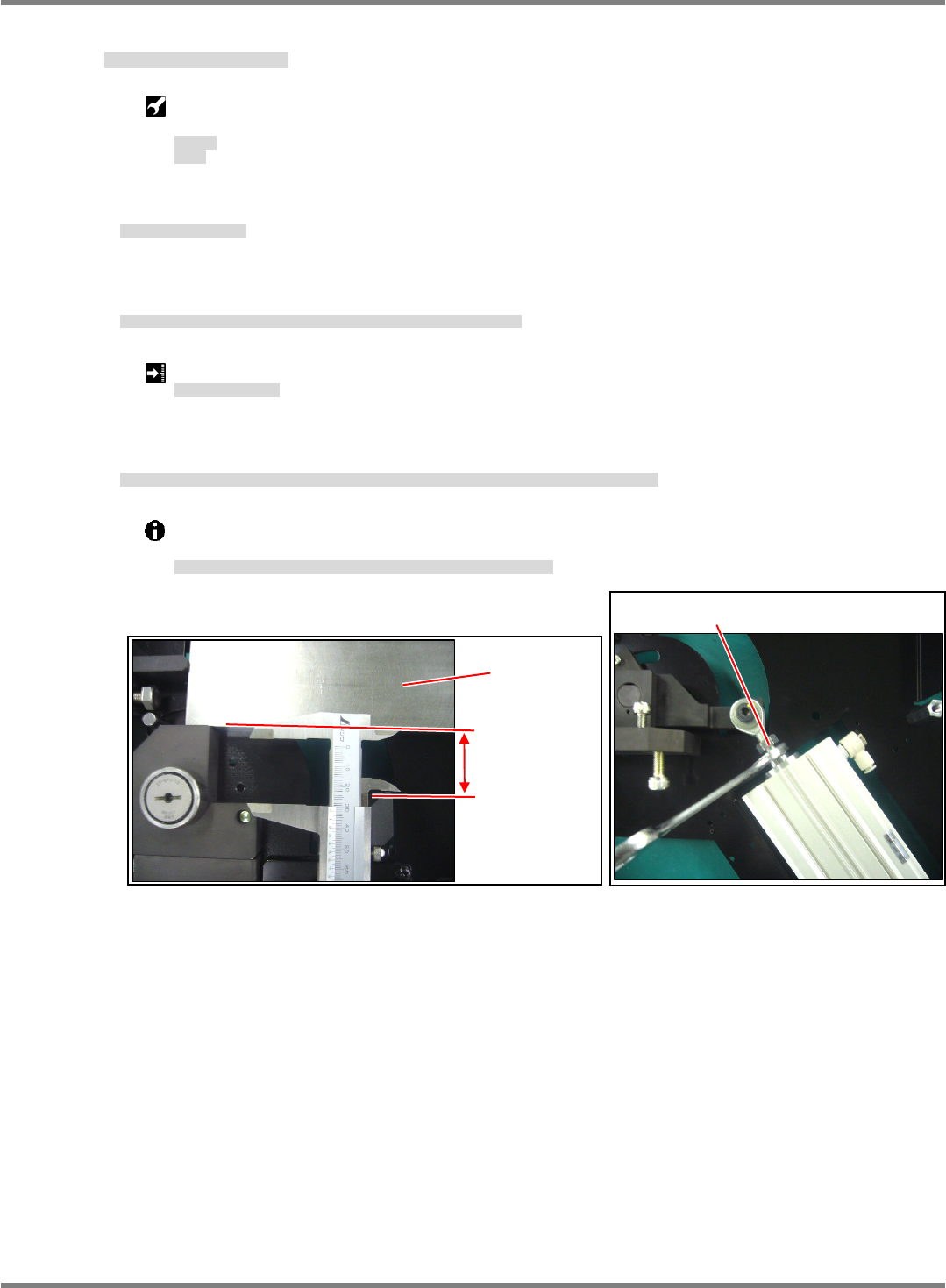
2. Set the block on the top face of the fulcrum block and measure the clearance to the tip of the clamper claw.
(Fig. 1)
始点ブロック上面にブロックを置き、クランパ爪先端のすき間を測定します。(Fig. 1)
将块放在开始点块的上面,测量夹具爪端部的间隙。(Fig. 1)
Clamp lever backward limit: 33.5
0.5 mm
クランプレバー後退限
夹具杆后退限
3. If the clamper tip clearance does not meet the requirement, adjust the penetration depth of the rod end on
the cylinder tip. (Fig. 2)
クランプレバー先端のすき間が規格外の場合は、シリンダ先端部ロッドエンドのねじ込み量で調整します。(Fig. 2)
夹具杆端部的间隙不在规格范围内时,通过汽缸端部的杆端部的拧紧量,进行调整。(Fig. 2)
If the guide is released, the block presses against the fulcrum block, making it possible to
measure dimensions accurately.
ガイドを外せばブロックが支点ブロックに密着し、正確な寸法を測定できます。
如果卸下导轨,块则靠紧在支点块上,由此可以测量正确的尺寸。
Fig. 2
Adjust the penetration depth of the rod end.
Fig. 1
Block
33.5
0.5 mm