NPM-D3维修手册.pdf - 第67页
NPM-D3 SERVICE MANUAL 4.3 Feeder Cart Unit EJM6D3-MB-04SM-02.DOC Page 4-29 4.3.2 Feeder Cart Connection 交換台車接続 交换台车的连接 Unit No. N610073093AA 4.3.1 Feeder Cart Handling U nit 交換台車駆動ユニット 交换台车驱动装置 4.3.2 Feeder Cart Connecti…
NPM-D3
SERVICE MANUAL
4.3 Feeder Cart Unit
Page 4-28 EJM6D3-MB-04SM-02.DOC
Fig. 2
Slide the guide to adjust the parallelism.
Stopper Bolt Parallelism Adjustment
ストッパーボルト平行度の調整
止动螺栓平行度的调整
Block
Dial gauge & magnet stand
ブロック
ダイヤルゲージ&マグネットスタンド
块
千分表和磁性支架
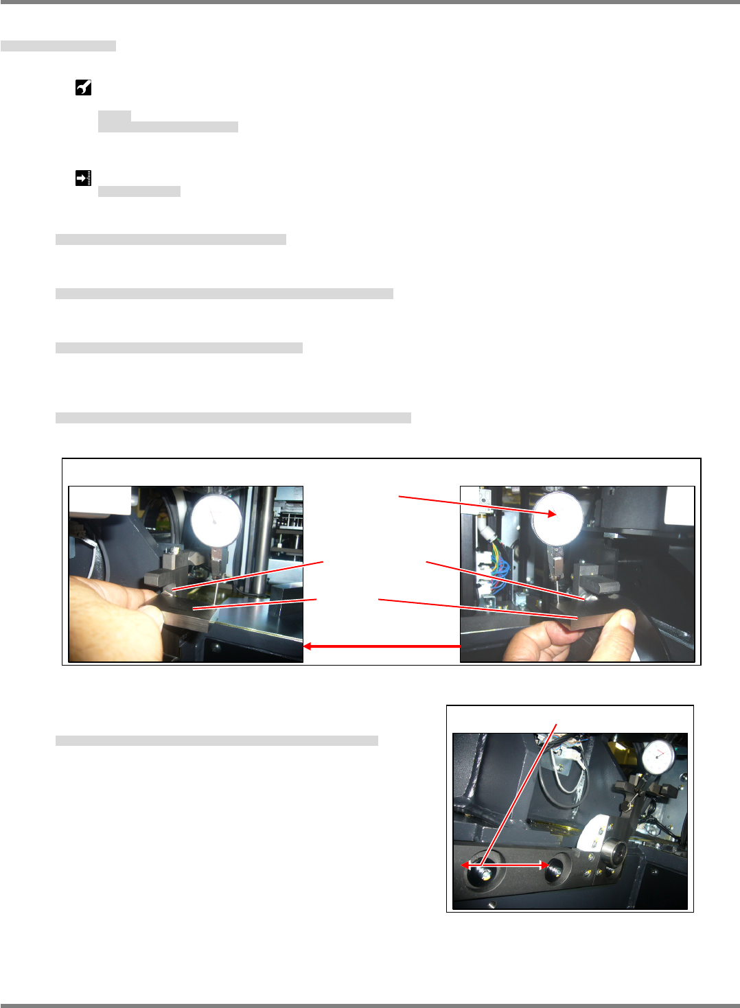
Stopper bolt parallelism:
0.02 mm
ストッパボルト平行度
止动螺栓平行度
11.
1. Attach a dial gauge to the X-axis using the magnet stand.
X軸にマグネットスタンドでダイヤルゲージを取り付けます。
用磁性支架,在 X 轴上安装千分表。
2. Set the block on the stopper bolt tip on the drive side, contact with the dial gauge and set 0.
駆動側のストッパボルト先端にブロックを置き、ダイヤルゲージを当て、0セットします。
在驱动侧的止动螺栓端部上放置块,贴上千分表,设定为 0。
3. Move the dial gauge attached to the X-axis to the guide side.
X軸に取り付けているダイヤルゲージをガイド側に移動させます。
将 X 轴上安装的千分表移动到导轨侧。
4. Set the block on the stopper bolt tip and measure the parallelism of the stopper bolt on the drive side using
the dial gauge. (Fig. 1)
ストッパボルト先端にブロックを置き、ダイヤルゲージで駆動側との平行を測定します。(Fig. 1)
在止动螺栓端部上放置块后,用千分表测量与驱动侧之间的平行度。(Fig. 1)
5. If the parallelism does not meet the requirement, slide the
guide back and forth to adjust the parallelism. (Fig. 2)
平行度が基準値外の場合は、ガイドを前後にスライドさせ平行度を調整します。(Fig. 2)
平行度不在基准值范围内时,将导轨前后滑动,调整平行度。(Fig. 2)
Fig.1
Block
Stopper bolt
Guide side
Set 0.
Drive side
NPM-D3
SERVICE MANUAL
4.3 Feeder Cart Unit
EJM6D3-MB-04SM-02.DOC Page 4-29
4.3.2 Feeder Cart Connection
交換台車接続
交换台车的连接
Unit No.
N610073093AA
4.3.1 Feeder Cart Handling Unit
交換台車駆動ユニット
交换台车驱动装置
4.3.2 Feeder Cart Connection
交換台車接続
交换台车的连接
Connector positioning jig
コネクタ位置調整治具
连接器位置调整治具
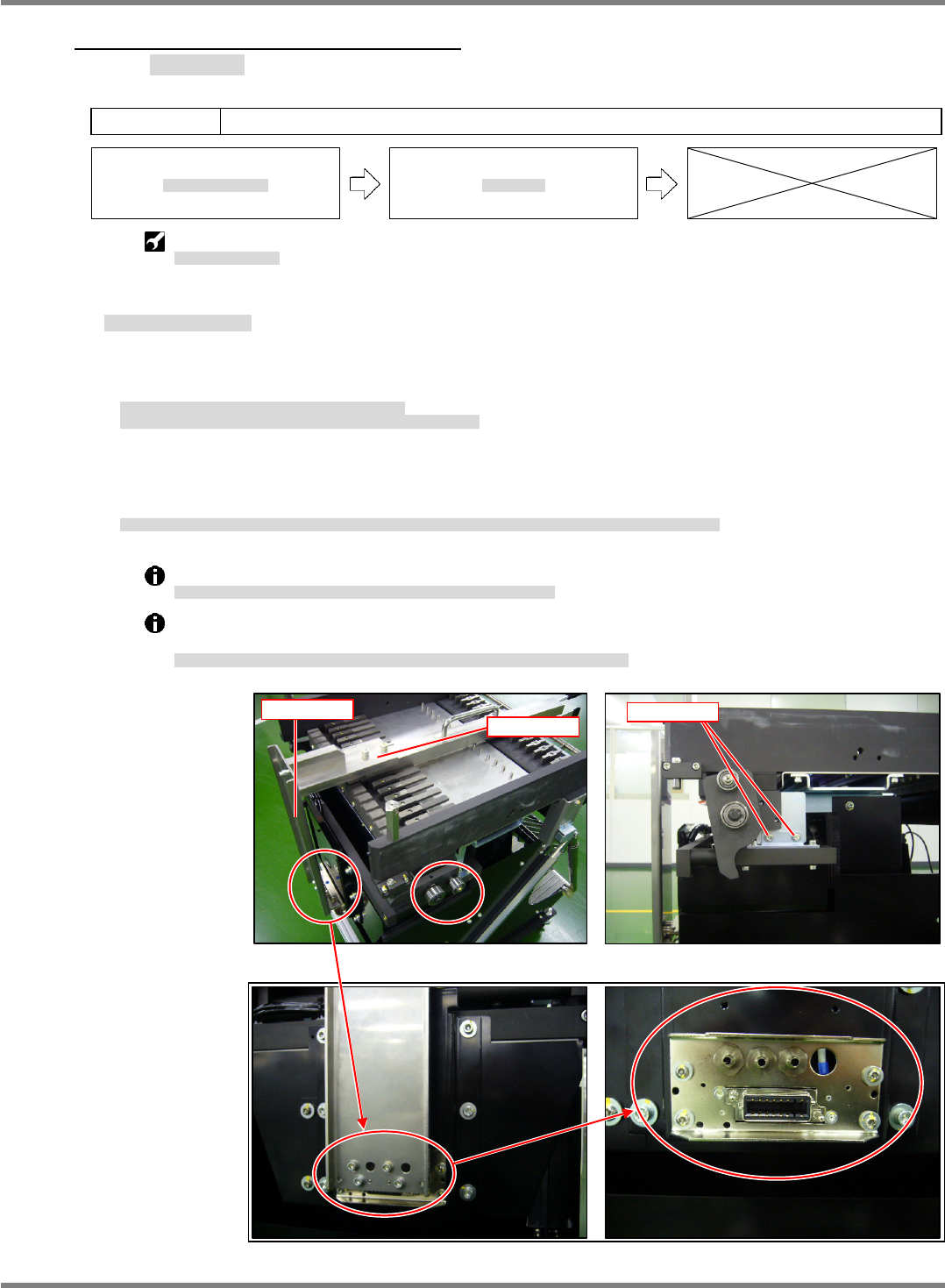
Feeder Cart Connector Position Adjustment
交換台車コネクタ位置調整
调整交换台车的连接器位置
12.
1. Insert the jig base into slot No. 9 on the feeder block.
Insert the jig plate into the connector and assemble to the jig base. (Fig. 1)
フィーダ搭載部の 9 番スロットに治具ベースを挿入します。
コネクタ部に治具プレートを挿入し、治具ベースと組み合わせます。(Fig. 1)
在料架搭载部的第 9 号插槽中插入治具基座。
在连接器部插入治具板后,并与治具基座组装。(Fig. 1)
2. If the jig base and jig plate do not mate, adjust the height, tilt, forward-reverse position and right-left position
of the connector installation bracket.
治具ベースと治具プレートが組み合わさらない場合は、コネクタ取り付け部の高さ、前後、左右、傾きをそれぞれ調整します。
不能组装治具基座和治具板时,分别调整连接器安装部的高度、前后、左右、以及倾斜度。
Adjust the connector height and forward-reverse position from the coupling bracket. (Fig. 2)
コネクタの高さ、前後方向については、連結ブラケット部で調整します。
(Fig. 2)
关于连接器的高度、前后方向,在连接托架部进行调整。
(Fig. 2)
Fine-adjust the connector right-left position, tilt and height from the front connector installation
bracket. (Fig. 3)
コネクタの左右、傾きと高さ方向の微調整は、前面のコネクタ取り付け部で調整します。
(Fig. 3)
关于连接器的左右、倾斜度以及高度方向的微调整,在前面的连接器安装部进行调整。
(Fig. 3)
Fig. 3
Fig. 1
Jig base
Jig plate
Fig. 2
Fixed parts
NPM-D3
SERVICE MANUAL
4.3 Feeder Cart Unit
Page 4-30 EJM6D3-MB-04SM-02.DOC
4.3.3 Tape Lift Detection Sensor
テープ浮き検出センサ
编带浮起检测传感器
Unit No.
N610073101AA
4.3.2 Feeder Cart Connection
交換台車接続
交换台车的连接
4.3.3 Tape Lift Detection Sensor
テープ浮き検出センサ
编带浮起检测传感器
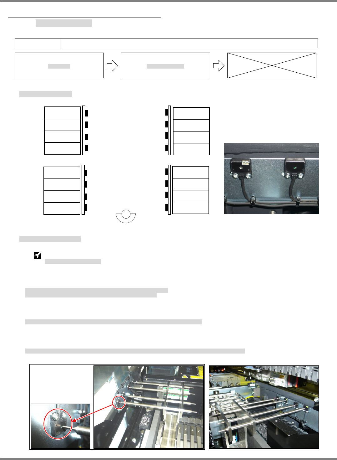
Tape Lift Detection Sensor Locations
テープ浮き検出センサ配置
编带浮起检测传感器的配置
Tape Lift Detection Sensor Position Adjustment
テープ浮き検出センサ位置調整
调整编带浮起检测传感器的位置
Tape lift sensor positioning jig set :
テープ浮きセンサ調整治具セット
成套编带浮起检测传感器调整治具
13.
1. Insert the tape lift sensor positioning jig base into slot No. 2 of the feeder block.
If the cover at the feeder tip contacts the jig base, detach the cover.
フィーダ搭載部の 2 番スロットにテープ浮きセンサ調整治具のベースを挿入します。
フィーダ先端部のカバーが治具ベースに当ります。カバーを外してください。
在供料器搭载部的第 2 号插槽中插入编带浮起传感器调整治具的基座。
料架端部的盖将会接触到治具基座上。请拆下盖。
2. Insert the jig shaft into the hole on the jig base and align the sensor lens with the shaft tip. (Fig. 1)
治具ベースの穴に治具シャフトを挿入し、シャフトの先端にセンサのレンズ位置を一致させます。(Fig. 1)
在治具基座的孔中插入治具轴,使传感器的镜头对准到轴的端部。(Fig. 1)
3. Insert the tape lift sensor positioning jig base into slot No. 16 and similarly align the sensor lens with the
shaft tip. (Fig. 2)
16 番スロットにテープ浮きセンサ調整治具のベースを挿入し、同様にシャフト先端とセンサのレンズ位置を一致させます。(Fig. 2)
在第 16 号插槽中插入编带浮起传感器调整治具的基座后,与上面同样,使传感器的镜头对准到轴的端部。(Fig. 2)
B1200TR
B1201R
B1202TR
B1203R
B1200R
B1201TR
B1202R
B1203TR
B1207R
B1206TR
B1205R
B1204TR
B1207TR
B1206R
B1205TR
B1204R
Detector Emitter
Fig. 2
Fig. 1