NPM-D3维修手册.pdf - 第72页
NPM-D3 SERVICE MANUAL 4.4 Nozzle Changer Page 4-34 EJM6D3-MB-04SM-02.DOC Head Option Drive Unit Assembly and Adjustment ヘッドオプション駆動ユニットの 組立調整 吸头选购件驱动装置的组装调整 If you loosen the base plate installation bolts or detach the …
NPM-D3
SERVICE MANUAL
4.4 Nozzle Changer
EJM6D3-MB-04SM-02.DOC Page 4-33
4.4 Nozzle Changer
ノズルチェンジャ部
吸嘴交换器部
4.4.1 Head Option Drive Unit
ヘッドオプション駆動ユニット
吸头选购件驱动装置
Unit No.
N610074583AA
4.4.1 Head Option Drive Unit
ヘッドオプション駆動ユニット
吸头选购件驱动装置
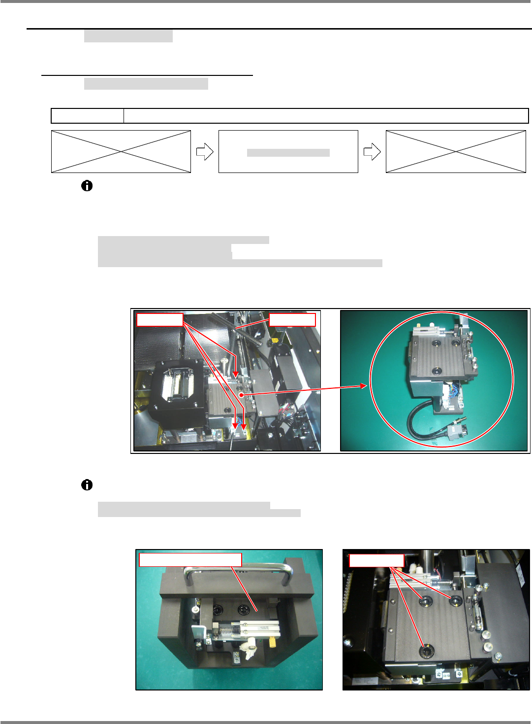
The Head Option drive unit is positioned with positioning pins.
It is anchored from above by bolt (3-M6 x 25).
(Bolts at the rear can be easily removed and tightened with a T-wrench.)
The head option drive unit is more easily detached by disconnecting wiring connectors and air
hoses at their relay connections. (Fig. 1)
ヘッドオプション駆動部は、規正ピンで位置決めされています。
上面からボルト
(3-M6
25)
で固定されています。
(
奥側は
T
型レンチを使用すると着脱が容易です。
)
配線コネクタとエアーホースを中継部分で外せば、ヘッドオプション駆動ユニットを取り外せます。
(Fig. 1)
吸头选购件驱动部被调整销定位。
从上面,被螺栓
(3-M6
25)
固定。
(
如果使用
T
型扳手,就容易装卸内侧。
)
如果在中继部分卸下配线连接器和空气软管,即可卸下吸头选购件驱动装置。
(Fig. 1)
The upper plate and cylinder are positioned with a jig. (Fig. 2)
Do not loosen the upper plate installation bolts (3-M10 x 16). (Fig. 3)
上部プレートとシリンダは治具で位置調整されています。
(Fig. 2)
特に上部プレートの固定ボルト
(3-M10
16)
は緩めないでください。
(Fig. 3)
上部板和汽缸的位置被治具调整。
(Fig. 2)
特别,请不要拧松上部板的固定螺栓
(3-M10
16)
。
(Fig. 3)
Fig. 1
T-wrench
3-M6
25
Fig. 2
Head option drive unit
Fig. 3
3-M10
16
NPM-D3
SERVICE MANUAL
4.4 Nozzle Changer
Page 4-34 EJM6D3-MB-04SM-02.DOC
Head Option Drive Unit Assembly and Adjustment
ヘッドオプション駆動ユニットの組立調整
吸头选购件驱动装置的组装调整
If you loosen the base plate installation bolts or detach the cylinder, assemble and adjust the
nozzle changer drive unit as follows.
ベースプレートの固定ボルトを緩めたり、シリンダを取り外した場合は、下記の要領で組立調整を行います。
已经拧松基座板的固定螺栓、或者卸下汽缸时,按照下面的步骤,进行组装和调整。
Block gauge set
ブロックゲージセット
块规组件
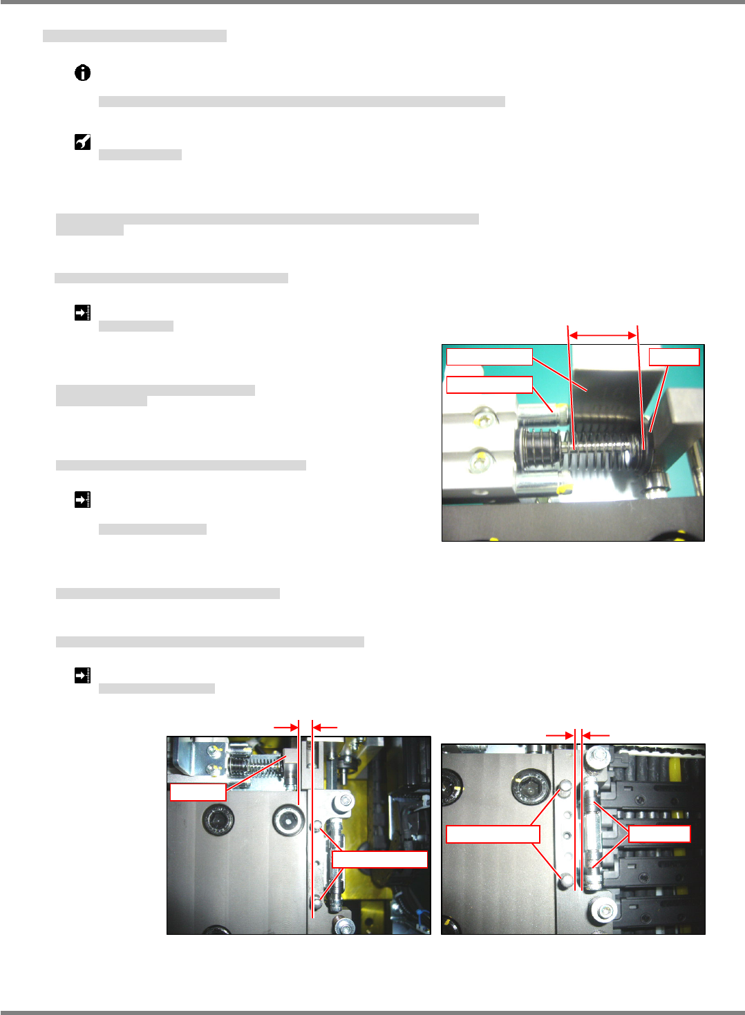
15.
1. Set the head option drive unit on a level surface, anchor the upper and lower ends of the base plate to the
surface and tight the installation bolts. (Fig. 1)
ヘッドオプションユニットを定盤上に置き、下部と上部のベースプレートの端面を定盤に密着させて固定ボルトを
締めます。(Fig. 1)
将吸头选购件装置放置在平台上,在使下部和上部的基座板的端面在紧贴到平台上的状态下,拧紧固定螺栓。(Fig. 1)
2. Measure the clearance between the tip of the stopper bolt and the collar. (Fig. 2)
ストッパーボルト先端とカラーのすき間を測定します。(Fig. 2)
测量止动螺栓的端部和轴环之间的间隙。(Fig. 2)
Cylinder stroke: 16
0.1 mm
シリンダストローク
汽缸行程
3. If the clearance does not meet the requirement, adjust the
penetration depth of the cylinder piston into the block.
基準値外の場合は、シリンダピストンのブロックへの
ねじ込みで調整します。
不在基准值范围内时,通过将汽缸活塞拧紧到块中时的拧紧量,进行调整。
4. Measure the clearance between the positioning pin and the
block at the end of the cylinder. (Fig. 3)
規正ピンとシリンダ先端のブロックのすき間を測定します。(Fig. 3)
测量调整销和汽缸端部的块之间的间隙。(Fig. 3)
Clearance between positioning pin and block: 5.5
0.1
mm
規正ピンとブロックのすき間
调整销和块之间的间隙
5. If the clearance does not meet the requirement, adjust the
installed position of the cylinder.
基準値外の場合は、シリンダの取り付け位置を調整します。
不在基准值范围内时,调整汽缸的安装位置。
6. Measure the clearance between the positioning pin and the cylinder block. (Fig. 4)
規正ピンとノズルチャンジャクランプのベアリングのすき間を測定します。(Fig. 4)
测量调整销和吸嘴夹具的轴承之间的间隙。(Fig. 4)
Clearance between positioning pin and bearing: Within 3 mm (Reference only).
規正ピンとベアリングのすき間
调整销和轴承之间的间隙
Fig. 2
16
0.1
Stopper bolt
Block gauge Collar
Fig. 3
5.5
0.1 mm
Positioning pin
Block
Fig. 4
3 mm
Bearing
Positioning pin
NPM-D3
SERVICE MANUAL
4.4 Nozzle Changer
EJM6D3-MB-04SM-02.DOC Page 4-35
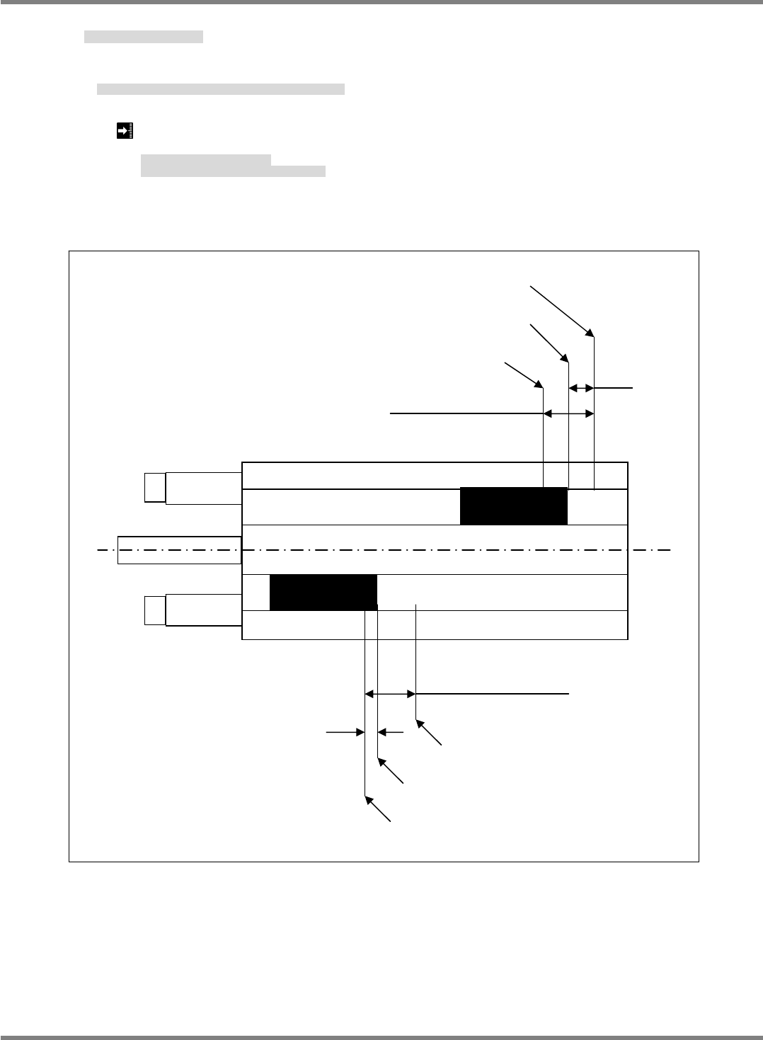
About 3 mm in the
range of detection
Switch position
Turns ON when approaching from left
Turns ON when approaching from right
1.5 mm
About 3mm in the
range of detection
1 mm
Turns ON when approaching from right
Switch position
Turns ON when approaching from left
Fig. 1
Cylinder Switch Position Adjustment
シリンダスイッチ位置調整
调整汽缸开关位置
16.
1. Adjust the position of the switch at the cylinder forward limit and return limit. (Fig. 1)
シリンダ行き限と戻り限のスイッチの位置を調整します。(Fig. 1)
调整汽缸往限度和返限度的开关的位置。(Fig. 1)
Cylinder forward limit: Center in the range of detection
Cylinder return limit : 1 mm from the rod side in the range of detection
シリンダ行き限
:
検出範囲の中心
シリンダ戻り限
:
検出範囲のロッド側から
1mm
汽缸往限度
:
检测范围的中心
汽缸返限度
:
离检测范围的杆侧
1 mm
的位置