OM-1646-001_w.pdf - 第82页
63 OM-1646 1005-001 17.Specications Item Description 5. Condi tions of PCB before Placement (Regulation of Component Height) Dual T ransfer Mode Single T ransfer Mode Height of Previously- Placed Component Upper Surfac…
62
OM-1646
1005-001
17.Specications
17.Specications
Item Description
1. Model Name GS-CU200
2. Applicable Model SIGMA-G5
3. PCB Flow
Direction
and Transfer
Reference
PCB Flow Direction : From Left to Right / From Right to Left
(Selected when shipped from the factory)
Transfer Reference : Front Left / Front Right
(Selected when shipped from the factory)
4. Applicable PCB
Mode Dual Transfer Mode Single Transfer Mode
Dimensions
X × Y
50 × 50 to 610 × 216 mm 50 × 50 to 610 ×
381 mm
Note : Four Corners : R1 to R1.5 mm
T
ickness
0.3 to 5.0 mm
Mass
Max. 1.5 kg (50 <= X <= 260 mm)
Max. 2.5 kg (260 < X <= 610 mm)
Material
Glass Epoxy
Ceramic (Option)
Notes : (a) In the case of ceramic, separate examination is required.
(b) D
epending on the PCB material, shape, warpage, mass or
surface condition (gloss), etc., it should be tested whether
or not the PCB can be transferred, or the components can
be placed normally, to conrm.
Warpage
0.2 mm or less per 50 mm (unit length)
Upper : Max. 1.0 mm
Lower : Max. 1.0 mm
• 0.2 mm or less per 50 mm (unit length)
Example: The warpage must be 0.8 mm or less when the PCB
size is 200 mm.
• Max. 1.0 mm
Example: The warpage must be 1.0 mm or less when the PCB
size exceeds 250 mm.
Warpage
63
OM-1646
1005-001
17.Specications
Item Description
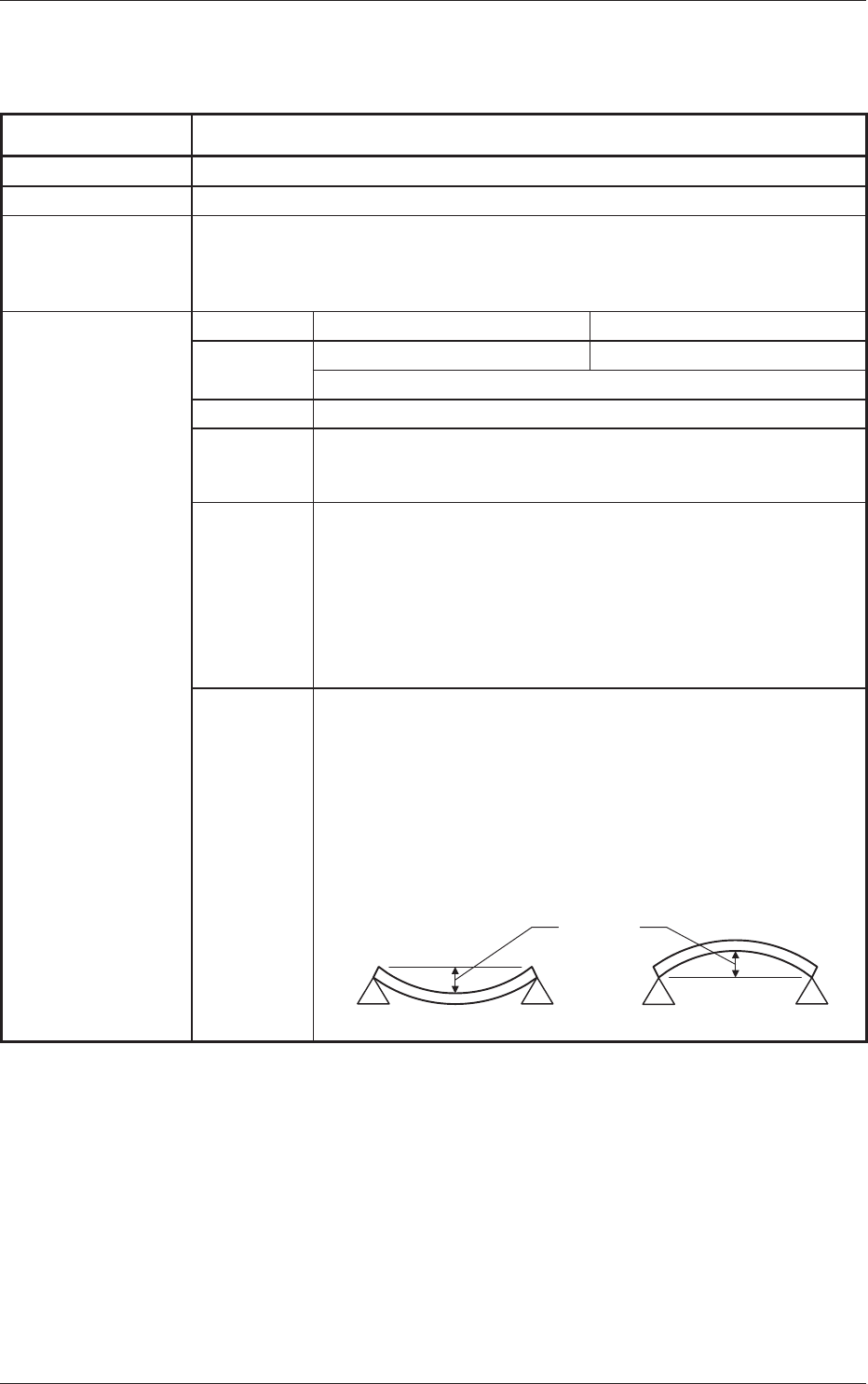
5. Conditions of PCB
before Placement
(Regulation
of Component
Height)
Dual Transfer Mode Single Transfer Mode
Height of
Previously-
Placed
Component
Upper Surface
12.7 mm / High-Speed Head
25.4 mm / Multifunctions Head
Lower Surface
30 mm
Dead Space
Upper Surface
3.0 mm
Lower Surface
3.0 mm
3.0
PCB
PCB Support Pin (At this position when
PCB is transfered.)
Previously-placed Components
Unallowed Range
Component
3.0
PCB Support Pin (Several Places)
φ5
φ2
4.0
3.0 3.0
When the
High-Speed
Head is used:
Max. 12.7
When the Multi-
Functional Head
is used:
Max. 25.4
Max. 30
(Front Side of Machine)
Unit : mm
Notes : (a) The gure shows that the PCB is being supported.
(b) Set the PCB support pin on the position where it does not touch the
already placed component.
(c) The dimensions are those for design reference.
Leave some room for the actual setting.
(d) PCB support pin position can be moved "10mm" by "10mm".
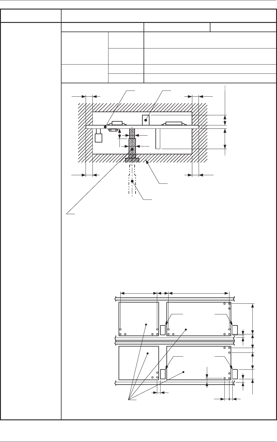
(e) For the positional relationship between the conveyor, PCB stopper and
backup base, refer to the following gure.
200
51
50
250 300
9
1030.5
5
10
Movable A
PCB
Positioning
Stopper
Backup Base
510
9
(Dual Transfer Mode, Flow Direction from left to right)
Movable A'
Movable B
Movable B'
PCB
Positioning
Stopper
Unit : mm
64
OM-1646
1005-001
17.Specications
Item Description
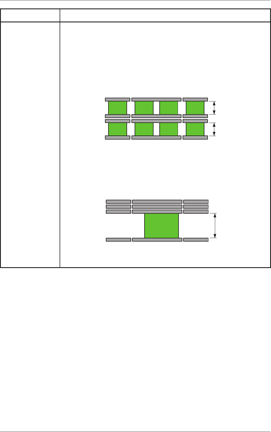
6. Transfer Mode When the PCB size is 216 mm or less, the dual transfer mode can be selected.
In the dual transfer mode, two transfer lanes are used. The single transfer mode can be
selected to transfer the PCBs exceeding 216 mm but not exceeding 381 mm.
When PCBs exceeding 216 mm must be produced, the single transfer mode is prepared
for convenience, making it possible to produce such PCBs.
• Dual Transfer Mode (Dual Transfer for Two PCBs at the same time)
PCB size 50 mm < Y <= 216 mm: In the case of transferring two PCBs:
The PCBs are transferred using the two lanes as the basic function of the dual
transfer system.
Max. 216 mm
Max. 216 mm
Movable A
Movable A'
Movable B
Fixed B'
Buffer Section Buffer Section
Front Side of Machine
Locating L/R Section
• Single Transfer Mode (Dual Transfer for Single PCB)
PCB Size 50 mm <= Y <= 381 mm: In the case of transferring one PCB:
The three rails (Movable A, Fixed A and Movable B) on the rear side are pushed
together to the rear and the single transfer is performed.
Max. 㪊㪏㪈 mm
Movable A
Movable A'
Movable B
Fixed B'
Buffer Section Buffer Section
Front Side of Machine
Locating L/R Section