OM-1646-001_w.pdf - 第16页
OM-1646 Cont-1 Contents Page 1005-001 Before Use ............................................................................................ 1 Caution and W arning .......................................................…
Safety Precautions
Safe-6
OM-1646
Alert Labels and Description
No. Alert Labels and Description
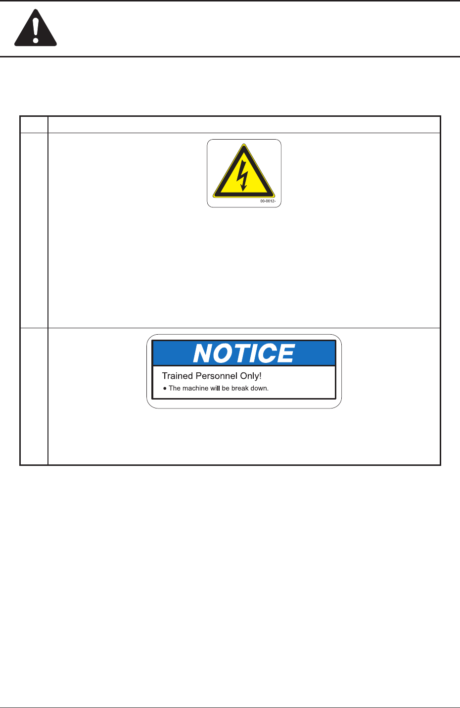
(1)
Description
This label indicates that high voltage is applied to the area. Residual voltages may
remain behind for a few minutes in the internal devices of the machine after power
interception.
Before performing maintenance work, wait until the charge lamps of the DC power
supply and the servoamplier go "OFF" in 10 minutes or more after the power
breaker is set to "OFF".
(2)
10-0252-
Description
If you put your hand or a heavy object on the backup table while working inside the
machine, the backup table may become deformed due to an excessive load.
1005-001
3. Alert Labels

OM-1646
Cont-1
Contents
Page
1005-001
Before Use ............................................................................................ 1
Caution and Warning ............................................................................ 3
Limited Warranty .............................................................................. 3
Installation/Transfer and After-Sale Service ..................................... 5
Requirements, Orientation, and Training for Operators ................... 5
AboutSpecicationChange ............................................................. 6
About Disposal of Machine .............................................................. 6
Other Precautionary Items ............................................................... 6
Safety Precautions
1. About Safety Precaution Labels ..................................................... Safe-1
2. Alert Indications in Instruction Manual............................................ Safe-3
Alert Indications described as " WARNING " .................................... Safe-3
Alert Indications described as " CAUTION " ..................................... Safe-3
3. Alert Labels .................................................................................... Safe-4
Location of
Alert Labels ..................................................................... Safe-5
Alert Labels and Description ............................................................. Safe-6
Contents .............................................................................................. Cont-1

OM-1646
Cont-2
Contents
Page
1005-001
1. Scope ............................................................................................. 1
2. Rough View of Machine ................................................................. 1
3. Automatic Operation ...................................................................... 2
3.1 "Line" Window ......................................................................... 5
3.2
"Run Mode" Tab Sheet ............................................................ 6
4. "PP CHANGE" Window .................................................................. 7
5. "SPRT-PINS CNVR Set-up" Window ............................................. 8
6. "PCB XFER" Window ..................................................................... 9
7. "PCB.CNT." Window....................................................................... 10
8. "INP/OUT" Window ........................................................................ 11
9. "MOTOR" Window .......................................................................... 12
10. CONVEYOR ................................................................................... 13
10.1 "Conveyor" Tab Sheet ............................................................. 14
10.2 "PCB Stpr." Tab Sheet ............................................................ 15
11. Program Change Operation ........................................................... 16
11.1 Selection of Run Mode ........................................................... 16
11.2 Selection of Operation Mode .................................................. 17
11.3 Collection of PCB Support Pins and
Setup Operation of Conveyor Width ................................ 18
11.4 ConrmationofPCBTransferandPositioning ....................... 19
12. Pattern Program ............................................................................. 21
12.1 Composition of Pattern Program ............................................ 21
12.2 Pattern Program Description .................................................. 22
12.2.1 Common Setting ............................................................ 22
13. Machine System ............................................................................. 24
13.1 "Chute Level" Window ............................................................ 25
13.2 "PCB Transfer Mode" Tab Sheet ............................................. 26