OM-1646-001_w.pdf - 第19页
OM-1646 Cont-4 Contents Page 1005-001 16. Pneumatic and Electrical Diagrams ............................................... 41 16.1 Pneumatic and Mounting Diagrams ........................................ 41 Conveyor (Pn…

OM-1646
Cont-3
Contents
Page
1005-001
14. Maintenance ................................................................................... 28
14.1 Outline of Maintenance ........................................................... 28
14.1.1 Notes on Maintenance ................................................... 2
8
14.1.2 Preparation for Maintenance ......................................... 29
14.1.2.1 Preparation for Cleaning ........................................ 29
14.1.2.2 Preparation for Lubrication ..................................... 30
14.1.3 Items for Periodic Maintenance ..................................... 33
14.2 Maintenance Check List ......................................................... 34
14.2.1 Weekly Maintenance ..................................................... 34
14.2.2 Quarterly Maintenance .................................................. 34
14.2.3 Half-Yearly Maintenance ............................................... 34
14.3 Maintenance Spots ................................................................. 35
14.3.1 Whole View .................................................................... 35
14.3.2 Inspection, Cleaning, and Lubrication stops .................. 36
14.3.2.1 PCB Positioning Section ........................................ 36
14.3.2.2 Conveyor Section ................................................... 37
15. List of Important Servicing Parts .................................................... 40

OM-1646
Cont-4
Contents
Page
1005-001
16. Pneumatic and Electrical Diagrams ............................................... 41
16.1 Pneumatic and Mounting Diagrams ........................................ 41
Conveyor (Pneumatic Diagram) .................................... 41
Conveyor (Mounting Diagram) ...................................... 42
16.2
Sensor and Load Layout ......................................................... 43
Conveyor Section Layout (Outside : A-Lane) ................ 43
Conveyor Section Layout (Outside : B-Lane) ................ 44
Conveyor Section Layout (Inside : A-Lane) ................... 45
Conveyor Section Layout (Inside : B-Lane) ................... 46
16.3 Parts Location ......................................................................... 47
Conveyor Section Layout .............................................. 47
16.4 Circuit Diagram ....................................................................... 48
Conveyor M Circuit Diagram (1) .................................... 48
Conveyor M Circuit Diagram (2) .................................... 49
Conveyor M Circuit Diagram (3) .................................... 50
Conveyor M Circuit Diagram (4) .................................... 51
Conveyor M Circuit Diagram (5) .................................... 52
Conveyor M Circuit Diagram (6) .................................... 53
Conveyor M Circuit Diagram (7) .................................... 54
Conveyor M Circuit Diagram (8) .................................... 55
Conveyor M Circuit Diagram (9) .................................... 56
Conveyor M Circuit Diagram (10) .................................. 57
U08 I/O P.C.B. STLT CNVR (L) ..................................... 58
U08 I/O P.C.B. STLT CNVR (R) ..................................... 59
16.5 Cable Connection Diagram ..................................................... 60
Dual Transfer Harness Connection Diagram 1 .............. 60
Dual Transfer Harness Connection Diagram 2 .............. 61
17. Specications ................................................................................. 62
1
OM-1646
1. Scope
In the dual transfer system, two lanes are used to transfer PCBs alternately,
assuming that the PCB transfer time is "0" (zero) and improving productivity.
Furthermore, this system can be used effectively to place components
simultaneously on different PCBs (for different models), reducing the
number of PCBs in the middle of processing and making it possible to make
appropriate production whenever necessary.
The transfer specications comply with the SMEMA transfer standards.
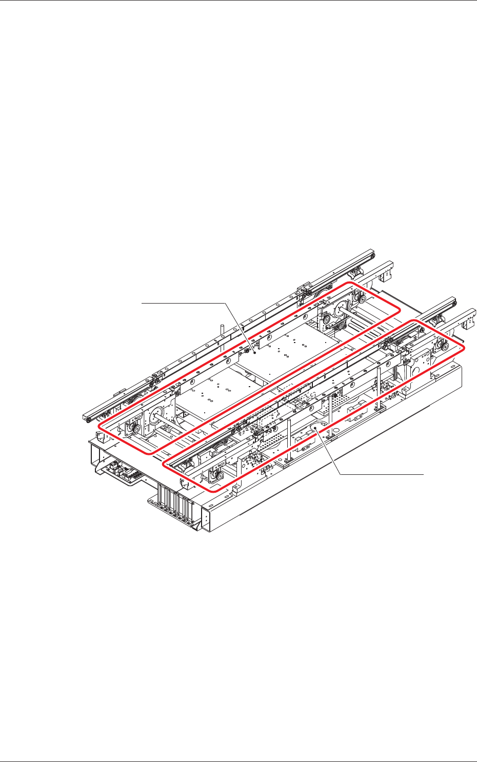
2. Rough View of Machine
Lane A
Lane B
Front Side of Machine
F1
1005-001
1. Scope